

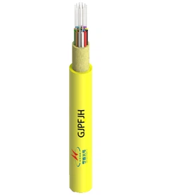



G.652.D is one of the most widely referenced standards for general-purpose single-mode optical fiber and cable. It combines established transmission characteristics with low-water-peak requirements, making it suitable for a broad range of telecom, access, metro, backbone, campus, and outside-plant networks.
For buyers and network designers, however, the label "G.652.D" is only the starting point. A real cable specification also needs to consider attenuation, mode field diameter, chromatic dispersion, polarization mode dispersion, cable construction, installation bend radius, operating wavelength, and the optical link budget.
If you need a broader introduction before comparing standards, see this overview of single-mode fiber.
G.652.D is an ITU-T single-mode fiber and cable category intended for general optical transmission. Its low-water-peak requirement controls attenuation around 1383 nm and supports use across portions of the extended 1260–1625 nm wavelength range. Where tight routing and bend loss are major concerns, G.657.A1 or G.657.A2 is usually the more relevant alternative.
As of this review, the current in-force recommendation is ITU-T G.652 (08/2024), approved on August 29, 2024.

What Is G.652.D Fiber?
G.652.D is a category within ITU-T Recommendation G.652, which defines geometrical, mechanical, and transmission attributes for single-mode optical fiber and cable. G.652 fiber was originally optimized around the 1310 nm region, where its zero-dispersion wavelength is located, but it can also operate in the 1550 nm region.
The "D" should be treated as an ITU-T subcategory designation rather than as a letter with a standalone technical meaning. What matters is the set of requirements associated with the category.
What does "low-water-peak" mean?
Older silica fibers could show elevated attenuation near 1383 nm because of hydroxyl-related absorption. G.652.D controls attenuation in this region, which is why it is commonly described as low-water-peak fiber.
Low water peak does not mean zero loss. The current G.652.D table specifies a maximum attenuation coefficient of 0.40 dB/km at 1383 nm ±3 nm after hydrogen ageing. This distinction is important because marketing phrases such as "zero water peak" can otherwise imply more than the standard actually requires.

Key G.652.D Fiber Specifications
The values below summarize several important limits in ITU-T G.652 (08/2024), Table 2.
| Parameter | G.652.D requirement |
|---|---|
| Mode field diameter measurement wavelength | 1310 nm |
| Nominal mode field diameter range | 8.6–9.2 μm |
| Mode field diameter tolerance | ±0.4 μm |
| Nominal cladding diameter | 125.0 μm |
| Cladding diameter tolerance | ±0.7 μm |
| Cable cut-off wavelength | ≤1260 nm |
| Macrobending test | 30 mm radius, 100 turns |
| Maximum macrobending loss at 1625 nm | 0.1 dB |
| Maximum attenuation from 1310–1625 nm | 0.40 dB/km, subject to the notes in the standard |
| Maximum attenuation at 1383 nm ±3 nm after hydrogen ageing | 0.40 dB/km |
| Maximum attenuation from 1530–1565 nm | 0.30 dB/km |
| Chromatic dispersion at 1550 nm | 13.3–18.6 ps/(nm·km) |
| Maximum PMD link design value | 0.20 ps/√km |
Primary source: ITU-T G.652 (08/2024). These values are standard limits, not guaranteed typical values for every commercial product.
Standard limits vs manufacturer typical values
This is one of the most important distinctions in procurement. A standard defines the boundary a compliant product must meet. A manufacturer may publish tighter maximum values or typical values for a particular fiber or cable design.
For example, if the standard permits a maximum attenuation of 0.40 dB/km over a specified wavelength region, a vendor datasheet may show a lower product-specific figure. That does not change the ITU-T limit; it describes the performance of that product. For engineering calculations, use the actual approved datasheet rather than substituting generic educational values.
When comparing products, it is useful to separate three fields in the specification: required standard, standard limit, and manufacturer guaranteed value. This avoids treating a typical value as if it were an international requirement.
Mode field diameter
Mode field diameter, or MFD, describes the effective region over which optical power propagates in a single-mode fiber. It is related to the core but is not simply another name for physical core diameter.
For G.652.D, the current ITU-T table gives a nominal MFD range of 8.6–9.2 μm at 1310 nm with a tolerance of ±0.4 μm. A single fixed value such as 10.1 μm may belong to a specific product, measurement condition, or older reference; it should not automatically be presented as the G.652.D standard value.
Attenuation and chromatic dispersion
Attenuation determines how much optical power is lost as light travels through the fiber. Chromatic dispersion describes how different spectral components of a signal propagate at slightly different speeds. Both matter when the link becomes longer or the transmission requirements become more demanding.
At 1550 nm, the current G.652.D chromatic-dispersion boundary is 13.3–18.6 ps/(nm·km). This does not prevent operation at 1550 nm; it means system design must account for accumulated dispersion. For a deeper explanation, see this guide to chromatic dispersion in optical fiber.
Polarization mode dispersion
Polarization mode dispersion, or PMD, can introduce differential delay between polarization components. ITU-T G.652.D specifies a maximum PMD link design value of 0.20 ps/√km under the statistical conditions defined by the recommendation.
PMD is only one part of link engineering, but it becomes increasingly relevant as bit rate, distance, and system margins become more demanding. This overview of polarization mode dispersion explains the parameter in more detail.
Macrobending test radius is not cable installation radius
G.652.D includes a fiber macrobending test using a 30 mm radius and 100 turns, with a maximum loss of 0.1 dB at 1625 nm. That value is a standardized fiber test condition. It is not a universal minimum installation bend radius for every finished G.652.D cable.
A cable's permitted bend radius depends on its complete construction, including jacket, strength members, armor, tube design, fiber count, and installation state. Always check both the minimum bend radius during installation and the minimum bend radius after installation on the specific cable datasheet.
What Are the Advantages of G.652.D Fiber?
1. A mature baseline for standard single-mode transmission
G.652 is a fundamental international reference for conventional single-mode optical transmission. For routes that do not require unusually tight bending, G.652.D provides a familiar baseline for equipment selection, splicing, testing, and network design.
2. Low-water-peak performance
The attenuation requirement around 1383 nm improves usability of spectral regions that were more restricted in legacy fiber designs. This can be useful when the optical system uses multiple wavelength bands.
3. Broad system flexibility
G.652.D can support operation across portions of the 1260–1625 nm range specified by the recommendation. However, usable wavelengths in a real network are determined by the complete system, including transceivers, multiplexers, splitters, amplifiers, connectors, and link loss. Fiber compliance alone is not a certification that every WDM design will work.
Where Is G.652.D Fiber Used?
G.652.D is best understood as a general-purpose single-mode transmission platform rather than a fiber intended for one narrow application.
- telecom transport networks;
- metro optical networks;
- access networks;
- backbone links;
- enterprise and campus fiber infrastructure;
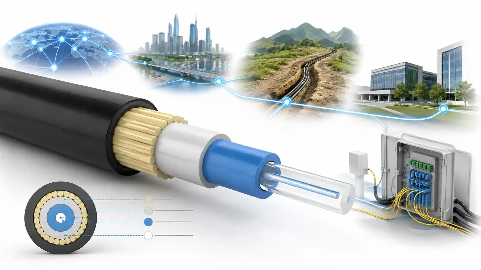
- outside-plant cable systems;
- WDM links when the complete optical system supports the required wavelength plan.
The practical selection question is not simply whether G.652.D can carry the signal. The real question is whether its optical characteristics and the chosen cable's mechanical construction fit the route, equipment, installation method, and future maintenance requirements.
G.652.D vs G.657.A1 vs G.657.A2
G.657 fiber is designed for improved macrobending performance. The current ITU-T G.657 (08/2024) recommendation states that Category A fibers are a subset of G.652.D requirements, are compliant with G.652.D, and have the same transmission and interconnection properties.
For a broader side-by-side discussion, see the site guide to G.652.D vs G.657.A1 vs G.657.A2.
| Selection factor | G.652.D | G.657.A1 | G.657.A2 |
|---|---|---|---|
| Primary design emphasis | Conventional single-mode transmission | Improved bend performance | Stronger bend tolerance |
| Relationship to G.652.D | Reference category | G.652.D compliant | G.652.D compliant |
| Bend-related reference | 30 mm fiber macrobending test radius; not a universal cable installation radius | 10 mm minimum design radius | 7.5 mm minimum design radius |
| Typical routing condition | Relatively open routes without demanding tight bends | Access, cabinets, and denser pathways | More space-constrained routing and tighter turns |
When should you choose G.652.D?
G.652.D is a logical baseline when the project requires standard single-mode transmission, routing is not mechanically demanding, and the selected cable construction already meets the installation environment.
When should you choose G.657.A1 or G.657.A2?
G.657 becomes more attractive when fibers must pass through tight pathways, compact distribution points, dense cabinets, building entry areas, or other locations where bend loss is a practical risk. G.657.A2 allows a smaller minimum design radius than G.657.A1.
For a product-level reference, review the specifications for G.657.A2 fiber alongside the actual cable construction being considered.
Can G.657.A be spliced into a G.652.D network?
Category A fiber is intended to remain compatible with G.652.D transmission and interconnection requirements. In practice, that makes G.657.A1 and G.657.A2 suitable options where tighter routing is needed within networks otherwise based on G.652.D.
That does not eliminate the need to qualify the actual products, splicing process, connector interfaces, and link budget. The standard relationship helps establish compatibility; project acceptance still depends on the complete installed system.

Is G.652.D the Same as OS2 Fiber?
No. The terms belong to different standardization frameworks and should not be treated as interchangeable.
ITU-T G.652 specifies attributes for single-mode optical fiber and cable. OS2, by contrast, is a cabled optical-fiber performance category used within structured cabling standards such as the ISO/IEC 11801 series.
A finished cable can therefore carry multiple relevant designations. Its optical fiber may comply with an ITU-T category such as G.652.D, while the cabling product is also classified under a structured-cabling performance category such as OS2.
When reviewing a datasheet, do not ask whether "G.652.D equals OS2." Instead, identify what each designation is describing and verify the requirements that apply to the complete cable and installation.
How to Specify G.652.D Cable for a Project
1. State the required standard and edition
Specify the required ITU-T category clearly and, when appropriate for the project, identify the applicable edition. For a new specification, referencing the current standard reduces ambiguity.
2. Separate standard compliance from product performance
Record both the standards requirement and the manufacturer-guaranteed values. Check attenuation, MFD, PMD, chromatic dispersion, environmental ratings, cable construction, temperature range, tensile performance, and any project-specific mechanical requirements.
If you are reviewing a commercial product, the G.652.D fiber product page is an example of where product-specific figures should be compared with the ITU-T limits rather than substituted for them.
3. Verify the finished cable bend radius
Do not reuse the 30 mm fiber test radius as a cable installation rule. Obtain the manufacturer's minimum bend radius during installation and after installation for the exact cable construction.
4. Match the fiber and cable to the optical system
Confirm the operating wavelength, link distance, transmitter power, receiver sensitivity, splice loss, connector loss, passive-component loss, and engineering margin. Testing and acceptance criteria should also match the project specification; this overview of fiber optic cable testing provides related context.
5. Consider future routing, not only the current route
A cable may begin in a relatively open outside-plant route and later enter cabinets, distribution frames, or tighter indoor pathways. If future routing is likely to become more constrained, comparing G.657.A1 or G.657.A2 at the design stage can reduce mechanical risk later.
Common G.652.D Misconceptions
"Every G.652.D fiber has a 10.1 μm MFD."
No. The current G.652.D table gives a nominal MFD range of 8.6–9.2 μm at 1310 nm with ±0.4 μm tolerance. A different number may describe a particular product or another measurement condition.
"30 mm is the installation bend radius of every G.652.D cable."
No. Thirty millimeters is part of the standardized fiber macrobending test condition. Finished cable bend limits come from the specific cable design and manufacturer.
"G.652.D cannot be used at 1550 nm."
Incorrect. ITU-T explicitly describes G.652 fiber as usable in the 1550 nm region. Chromatic dispersion is higher there than near the 1310 nm zero-dispersion region, so the system must be designed accordingly.
"Low-water-peak means zero attenuation around 1383 nm."
No. G.652.D sets a defined maximum attenuation requirement in that region; it does not imply zero transmission loss.
Frequently Asked Questions
What wavelength range does G.652.D cover?
The current recommendation defines relevant transmission requirements across portions of the extended 1260–1625 nm range. Actual operating wavelengths still depend on the complete optical system.
Is G.652.D suitable for CWDM?
It can be suitable because of its low-water-peak and extended-wavelength characteristics, but CWDM compatibility is a system-level decision. Transceivers, multiplexers, wavelength plan, passive components, and total link loss must all support the intended channels.
Is G.652.D bend-insensitive fiber?
Not in the same sense as G.657. If tight bends are a design requirement, evaluate G.657.A1 or G.657.A2 rather than relying on the G.652.D macrobending test alone.
What should a buyer verify before ordering G.652.D cable?
Verify the stated standards compliance, actual product attenuation and MFD, PMD and dispersion data, cable construction, environmental ratings, installation and long-term bend radii, and the complete optical power budget.
Conclusion: When Should You Choose G.652.D?
G.652.D remains a strong baseline for general-purpose single-mode optical infrastructure. It offers standardized transmission characteristics, low-water-peak performance, and broad applicability across telecom, access, metro, backbone, campus, and outside-plant networks.
Choose G.652.D when conventional single-mode transmission is the main requirement and the route does not demand unusually tight bending. Compare G.657.A1 or G.657.A2 when space, cabinets, closures, or indoor routing create a higher bend-loss risk.
Most importantly, treat G.652.D as one part of the cable specification, not the entire specification. Before procurement, verify the manufacturer's actual cable datasheet, installation limits, environmental construction, optical performance, and link-budget assumptions.