





You demand reliable, high-speed data transmission from your optical fiber network. Signal quality can drop unexpectedly, even when you use advanced hardware. Polarization Mode Dispersion often causes this degradation. If you overlook PMD, you risk increased bit errors, reduced bandwidth, and costly downtime. You need to understand, measure, and control PMD to ensure your network performs at its best.
Key Takeaways
- Understand that Polarization Mode Dispersion (PMD) can increase bit error rates, leading to data loss.
- Recognize that PMD limits your network's maximum data rate, impacting overall performance.
- Regularly measure PMD to detect early signs of signal degradation and maintain compliance with industry standards.
- Choose low-PMD fibers for new installations to support high-speed networks and reduce future risks.
- Implement both passive and active PMD management strategies to ensure reliable signal quality.
- Monitor environmental factors that can affect PMD, such as temperature changes and mechanical stress.
- Invest in AI-driven monitoring tools to catch PMD-related issues before they impact service quality.
- Stay informed about industry standards like ITU-T G.652 to ensure your network meets compliance requirements.
PMD and Signal Quality
Polarization Mode Dispersion directly impacts the quality of your optical signals, especially as you push your network to higher speeds. You need to understand how PMD causes signal degradation and why it becomes a critical concern in modern, high-capacity systems.

Signal Degradation
Bit Errors
When you transmit data through optical fiber, you expect each bit to arrive clearly and accurately. However, Polarization Mode Dispersion introduces a time delay between two orthogonal polarization components of light. This delay results from imperfections in the fiber, such as core ellipticity or uneven stress, which cause each polarization state to travel at a different speed. As a result, the light pulse spreads out and distorts by the time it reaches the receiver.
If you operate a high-speed network, even a small amount of PMD can increase your bit error rate (BER). Experimental data shows that as PMD increases, the BER rises sharply. This happens because the receiver struggles to distinguish between overlapping pulses, leading to more errors in the decoded data. In real-world scenarios, network operators often notice unexplained spikes in BER during periods of environmental change, such as temperature fluctuations or physical disturbances to the fiber.
Pulse Broadening
Pulse broadening is another direct consequence of Polarization Mode Dispersion. In an ideal fiber, both polarization states would travel at the same speed, keeping the light pulse compact and well-defined. However, due to PMD, the pulse spreads out over time. This broadening causes adjacent pulses to overlap, making it difficult for your receiver to separate individual bits.
- PMD arises from the differential speeds of two orthogonal polarization components.
- This speed difference leads to time delays and pulse spreading.
- The outcome is pulse broadening and distortion, which can corrupt data and reduce signal quality.
You may notice this effect as a gradual decline in network performance, especially as you increase the data rate. Over time, pulse broadening can force you to reduce your system's speed or invest in costly compensation technologies.
High-Speed Network Impact
Data Integrity
As you upgrade your network to support 10 Gbps, 40 Gbps, or even 100 Gbps, the effects of Polarization Mode Dispersion become more pronounced. At higher bit rates, the time window for each bit shrinks, so even minor delays caused by PMD can lead to significant data corruption. This threatens the integrity of your transmitted information, which is especially critical for financial transactions, healthcare data, or real-time communications.
|
Bit Rate (Gbps) |
PMD Coefficient (ps/km) |
Performance Impact |
|---|---|---|
|
10 |
2 |
Significant degradation |
|
40 |
2 |
Increased bit error rate |
|
100 |
0.1 |
Some impact on signal quality |
You can see from the table above that even at a low PMD coefficient, high-speed systems experience noticeable performance penalties. This means you must pay close attention to PMD as you scale your network.
Transmission Limits
PMD sets a hard limit on how far and how fast you can transmit data over your optical fiber. As the bit rate increases, the tolerance for PMD decreases. If you ignore PMD, you risk reaching a point where your network cannot support higher speeds or longer distances without unacceptable signal loss.
- Imperfections in the fiber, such as core ellipticity and uneven stress, cause the two polarization states to travel at different speeds.
- This leads to a time difference between the two components, resulting in light pulse spreading.
- The distortion at the receiver can corrupt data and reduce overall signal quality.
For network operators, this means you must regularly monitor PMD and take proactive steps to manage it. If you fail to address PMD, you may face costly downtime, service interruptions, or the need for expensive upgrades.
In summary, Polarization Mode Dispersion is not just a technical detail-it is a critical factor that determines the reliability and capacity of your optical network. By understanding how PMD affects signal quality, you can make informed decisions to protect your data and maintain high performance.
Polarization Mode Dispersion Explained

Definition
Polarization Mode Dispersion describes how different polarization states of light travel at different speeds through an optical fiber. You encounter this effect because real-world fibers are not perfect. Each polarization mode, or direction in which light vibrates, can move at a slightly different rate. This difference causes the light pulse to spread out as it moves down the fiber, which can degrade your signal.
Group Velocity Dispersion
Group velocity dispersion refers to the variation in speed at which different parts of a light pulse travel. In your optical fiber, this means that the two main polarization modes do not arrive at the receiver at the same time. The time difference between these modes is called Differential Group Delay (DGD). When DGD increases, your system experiences more pulse broadening and higher bit error rates. At higher data rates, even small amounts of group velocity dispersion can cause significant problems, making it harder for your network to maintain clear and accurate signals.
Orthogonal Polarizations
Light in an optical fiber can be split into two orthogonal polarization states. In an ideal fiber, both would travel at the same speed. However, imperfections in the fiber cause these two states to move at different velocities. This leads to a spreading of the light pulse, which you see as Polarization Mode Dispersion. The more your system relies on high-speed data, the more sensitive it becomes to these differences.
Causes
You need to understand what causes Polarization Mode Dispersion to manage it effectively. Both the physical properties of the fiber and the environment around it play key roles.
Fiber Imperfections
The core of an ideal optical fiber should be perfectly circular, but manufacturing processes often introduce slight imperfections.
These imperfections create birefringence, a phenomenon where the fiber has different refractive indices for different polarization states.
Birefringence causes each polarization mode to travel at a different speed.
Asymmetries in the fiber, such as elliptical cross sections, microbends, and microtwists, increase birefringence along the fiber length.
Mechanical stresses from bending or pressure can deform the fiber, making one polarization mode faster than the other.
These factors combine to create random coupling between the two polarization modes, which leads to Polarization Mode Dispersion and signal degradation.
Environmental Factors
PMD changes rapidly when the environment changes. Temperature fluctuations, mechanical vibrations, and wind can all affect your fiber. These external factors introduce bending, pressure, or twists, which alter the Differential Group Delay and increase Polarization Mode Dispersion.
You may notice that your network's performance drops during extreme weather or when cables experience physical stress. Monitoring these environmental factors helps you predict and manage PMD-related issues.
Why does PMD matter more at higher data rates?
As you increase your network's speed, the time window for each bit shrinks. Even a small delay between polarization modes can cause pulses to overlap, leading to errors. High-speed systems demand tighter control over PMD to maintain data integrity and avoid costly downtime.
PMD and System Performance

Reliability
Service Interruptions
You rely on your optical network to deliver uninterrupted service. When Polarization Mode Dispersion increases, your system faces a higher risk of signal degradation. This can cause sudden service interruptions, especially in long-haul and metro networks where distances amplify the effects. Even a brief disruption can impact critical applications like financial transactions, emergency communications, or cloud services. You may notice alarms, dropped connections, or the need for manual resets. These interruptions often trace back to unpredictable changes in PMD, which can spike during temperature swings or after physical disturbances to the fiber.
Downtime Risks
Downtime poses a direct threat to your business operations and reputation. As PMD grows, so does the bit error rate (BER), making your network less reliable. The table below highlights the relationship between PMD and reliability in different network types:
|
Parameter |
Description |
|---|---|
|
PMD |
A crucial parameter affecting reliability in optical networks |
|
Impact |
Leads to signal degradation, increasing bit error rate (BER) |
|
Application |
Significant in long-haul and metro optical networks |
You face higher maintenance costs and customer complaints when downtime increases. In competitive markets, even a few minutes of outage can drive users to alternative providers. By monitoring and managing PMD, you reduce the risk of costly downtime and maintain your service level agreements.
Tip: Regular PMD testing helps you detect early warning signs before they escalate into major outages.
Compliance
Industry Standards
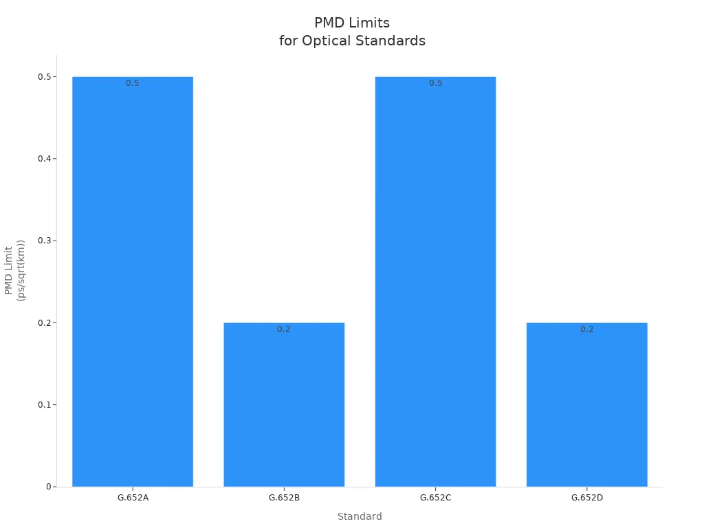
You must meet strict industry standards to ensure your network qualifies as carrier-grade. International standards, such as ITU-T G.652, specify acceptable PMD limits for different fiber types. The table below summarizes these limits:
|
Standard |
PMD Limit (ps/sqrt(km)) |
|---|---|
|
G.652A |
<= 0.5 |
|
G.652B |
<= 0.2 |
|
G.652C |
<= 0.5 |
|
G.652D |
<= 0.2 |
These standards protect your network from excessive signal degradation and ensure compatibility with global infrastructure. If your fiber exceeds these PMD limits, you risk failing compliance audits and facing penalties.
Carrier-Grade Requirements
Carrier-grade networks demand high reliability, low error rates, and minimal downtime. Meeting PMD standards is not optional-it is essential for maintaining your competitive edge. You must document compliance, perform regular PMD measurements, and upgrade fibers that do not meet the latest requirements. By doing so, you assure your customers of consistent, high-quality service.
Note: Investing in low-PMD fiber and proactive monitoring tools helps you stay ahead of compliance requirements and avoid unexpected failures.
Measuring Polarization Mode Dispersion

Accurate measurement of Polarization Mode Dispersion (PMD) is essential for maintaining high-quality optical networks. You need to know how to measure PMD, interpret the results, and use this information to make informed decisions about network maintenance and upgrades.
Measurement Techniques
You have several reliable methods to measure PMD in your fiber links. Each method offers unique advantages for different network scenarios.
Interferometric Methods
Interferometric techniques remain a popular choice for Polarization Mode Dispersion (PMD) measurement. You use these methods to analyze the time delay between two orthogonal polarization modes. Instruments like the EXFO PMD FTB-5500B Analyzer help you collect Differential Group Delay (DGD) data over time. This approach allows you to observe how environmental factors-such as temperature changes or wind-impact the state of polarization in your fiber. By monitoring these variations, you can identify periods of increased Polarization Mode Dispersion risk and plan maintenance accordingly.
Interferometric methods provide high accuracy for long-term Polarization Mode Dispersion monitoring.
You can detect sudden changes caused by environmental stress or fiber movement.
Stokes Parameter Methods
Stokes parameter methods offer another effective way to measure Polarization Mode Dispersion (PMD). These techniques analyze the polarization state of light as it travels through the fiber. By measuring the Stokes parameters, you can determine the Differential Group Delay (DGD) and the overall Polarization Mode Dispersion coefficient. This method works well for both laboratory and field environments, giving you flexibility in your testing strategy.
Tip: Use Stokes parameter methods when you need fast, real-time PMD measurements during network commissioning or troubleshooting.
Interpreting Results
Once you have collected PMD data, you must interpret the results to ensure your network meets performance standards.
Acceptable Thresholds
You should compare your PMD measurements to industry benchmarks. The table below shows typical maximum PMD values for different bit rates and network types:
|
Bit Rate (Gbit/s) |
Max. PMD (ps) |
PMD Coefficient (ps/(√km)) |
|---|---|---|
|
2.5 |
40 |
<2.0 |
|
10 |
10 (no FEC) |
<0.5 |
|
20 |
5 |
<0.25 |
|
40 |
2.5 |
<0.125 |
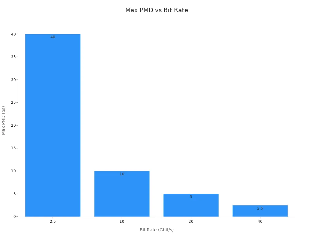
If your PMD values exceed these thresholds, you risk increased bit errors and reduced network reliability. You should act quickly to address any sections of fiber that approach or surpass these limits.
Practical Implications
Interpreting PMD results helps you target maintenance and upgrades where they matter most. The table below summarizes how you can use PMD data to improve your network:
|
Feature |
Description |
|---|---|
|
Locates fiber sections |
Identifies sections contributing significantly to total PMD |
|
Isolates and repairs |
Focuses on the worst PMD sections for maintenance |
|
Cost-effective upgrades |
Enables upgrades of fiber networks limited by PMD |
|
Identifies performance changes |
Helps find small changes that can enhance network performance |
By focusing on the most problematic fiber sections, you save time and resources. You also ensure your network supports higher data rates and meets customer expectations for reliability.
Regular PMD measurement and analysis give you the insight needed to maintain a robust, future-ready optical network.
Managing and Mitigating PMD
Effectively managing and mitigating PMD ensures your optical network delivers reliable, high-speed performance. You need to make informed choices about fiber selection, compensation technologies, and ongoing maintenance to minimize the risks associated with Polarization Mode Dispersion.

Fiber Selection
Low-PMD Fibers
You can reduce Polarization Mode Dispersion (PMD) at the source by choosing low-PMD fibers during network design or upgrades. Manufacturers produce these fibers with tighter control over core geometry and stress, resulting in lower birefringence and more consistent performance. Low-PMD fibers typically have a Polarization Mode Dispersion coefficient below 0.1 ps/√km, which supports 100G and higher data rates over long distances. When you invest in these fibers, you future-proof your network and avoid costly retrofits as bandwidth demands grow.
Installation Best Practices
Proper installation plays a critical role in minimizing PMD. You should:
- Avoid excessive bending and twisting during cable placement.
- Use gentle cable management to prevent microbends and stress points.
- Ensure connectors and splices are clean and properly aligned.
Tip: Train your installation teams on best practices and monitor their work to maintain low PMD levels throughout your network.
Compensation Technologies
You can deploy compensation technologies to address PMD in existing fiber infrastructure, especially when replacing fiber is not feasible.
Electronic Solutions
Electronic compensation offers flexible and scalable options for Polarization Mode Dispersion (PMD) mitigation in high-speed networks. You can choose from several approaches:
- Per-channel optical PMD compensators (PMDCs) target individual wavelengths.
- Analog and digital electronic PMDCs process signals to correct Polarization Mode Dispersion–induced distortions.
- All-channel mitigation methods use distributed fast polarization scrambling and forward error correction (FEC) to enhance signal integrity.
- Digital coherent detection enables advanced digital PMDC techniques, allowing your system to adapt dynamically to changing Polarization Mode Dispersion conditions.
These solutions help you maintain low bit error rates and stable performance, even as network speeds increase.
Optical Devices
Optical devices provide another layer of PMD compensation. The table below summarizes common types and their operational principles:
|
Type of PMD Compensator |
Operational Principle |
|---|---|
|
Optical PMD Compensators |
Utilize feedback signals and may involve complex multistage structures for mitigation |
|
Electrical PMD Compensators |
Employ electronic equalization techniques, including linear and Viterbi equalizers |
You can combine optical and electronic compensators for robust, multi-layered PMD management. This approach gives you flexibility to address both static and dynamic PMD effects in your network.
Maintenance
Ongoing maintenance and monitoring are essential for long-term PMD control. You need to adopt proactive strategies to keep your network performing at its best.
Monitoring
Regular Polarization Mode Dispersion (PMD) monitoring helps you detect issues before they impact service quality. Enhanced monitoring systems, especially those with mobile access, improve your response time and decision-making.The table below highlights the benefits of proactive maintenance and monitoring:
|
Evidence Type |
Description |
|---|---|
|
Reduced Downtime |
Proactive maintenance can reduce asset downtime by 35% to 45% and decrease breakdowns by 70% to 75%. |
|
Extended Asset Lifespan |
Deferred maintenance spending can lead to a 4X increase in future costs. |
|
Cost Savings |
Unplanned maintenance costs three to five times more than planned maintenance. |
|
Enhanced Monitoring and Mobile Access |
73% of facility services providers report improved work order response time due to mobile technology. |
|
Improved Decision-Making |
Integrated systems provide valuable insights to align maintenance with business goals. |
|
Improved Compliance and Safety |
Planned maintenance enhances workplace safety and supports sustainability initiatives. |
Note: By investing in regular PMD monitoring, you reduce downtime, extend asset life, and save on operational costs.
Upgrades
Upgrading legacy fiber infrastructure can dramatically reduce PMD and support higher data rates. You have several effective strategies:
|
Strategy |
Benefits |
|---|---|
|
Virtualization |
Enables faster upgrades, flexible network architecture, easier capacity management, and better visibility. |
|
Distributed Access Architecture (DAA) |
Complements virtualization, supports multiple architectures, and extends the life of existing infrastructure. |
|
Modern solutions |
Provide versatility for plant extensions, support for 10G PON fiber, and alleviate operational challenges. |
You should evaluate your network's needs and select upgrade paths that align with your business goals and future growth plans.
Scenario: If you operate a metro network with legacy fiber, combining virtualization and DAA can help you scale to 100G and beyond without full fiber replacement.
By focusing on fiber selection, compensation technologies, and proactive maintenance, you ensure your network remains resilient against the challenges of Polarization Mode Dispersion.
PMD Management Approaches

Passive vs. Active
When you manage Polarization Mode Dispersion (PMD) in optical fiber networks, you face a choice between passive and active approaches. Understanding why each method works differently helps you select the best strategy for your network's signal quality and reliability.
Passive PMD management relies on the inherent properties of your optical fiber and careful installation. You use low-PMD fiber, follow strict installation guidelines, and minimize environmental stress. This approach requires little intervention after deployment. You benefit from lower operational costs and reduced complexity. However, passive methods cannot adapt to sudden changes in PMD caused by temperature shifts or physical disturbances.
Active PMD management uses real-time monitoring and compensation devices. You install electronic or optical compensators that detect and correct Polarization Mode Dispersion as it occurs. This hands-on approach gives you greater control over signal quality, especially in high-speed or long-haul networks. You can respond quickly to environmental changes and maintain optimal performance.
The table below highlights key differences between passive and active PMD management:
|
Feature |
Passive Management |
Active Management |
|---|---|---|
|
Goal |
Maintain stable PMD with minimal intervention |
Continuously correct PMD for best signal quality |
|
Management Style |
Hands-off, relies on fiber quality |
Hands-on, uses real-time compensation |
|
Costs |
Lower, due to minimal equipment and labor |
Higher, due to advanced devices and monitoring |
|
Risk Level |
Stable under normal conditions |
Handles higher risk from dynamic PMD changes |
|
Transparency |
Highly predictable performance |
Performance depends on system and operator skill |
Tip: Choose passive management for stable, low-speed networks. Use active management when you need to support high data rates or unpredictable environments.
Pros and Cons
You need to weigh the pros and cons of each approach before making a decision.
Passive Management Pros:
- Lower initial and ongoing costs
- Simple operation and maintenance
- High reliability in stable environments
Passive Management Cons:
- Limited adaptability to sudden PMD changes
- May not support future upgrades to higher speeds
Active Management Pros:
- Real-time correction of PMD
- Supports higher data rates and longer distances
- Adapts to environmental changes
Active Management Cons:
- Higher capital and operational expenses
- Increased system complexity
- Requires skilled personnel for setup and monitoring
Scenario: If you operate a metro network with frequent temperature swings, active PMD management ensures consistent signal quality. For a short, stable campus network, passive management may suffice.
Cost and Complexity
Managing PMD in optical fiber networks involves both financial and operational considerations. You must understand why cost and complexity differ between short-term and long-term strategies.
Short-Term vs. Long-Term
In the short term, passive Polarization Mode Dispersion (PMD) management offers a cost-effective solution. You invest in high-quality, low-PMD fiber and proper installation. This approach minimizes upfront expenses and keeps maintenance simple. However, as your network grows or data rates increase, passive methods may struggle to keep up with new Polarization Mode Dispersion demands.
Active Polarization Mode Dispersion (PMD) management requires a larger initial investment. You purchase compensation devices, monitoring systems, and train your staff. These costs can seem high at first. Over time, though, active Polarization Mode Dispersion management protects your network from costly downtime and service interruptions. You also gain flexibility to upgrade to 100G or 400G systems without replacing your entire fiber plant.
|
Approach |
Short-Term Cost |
Long-Term Cost |
Complexity |
Upgrade Flexibility |
|---|---|---|---|---|
|
Passive |
Low |
Can increase |
Low |
Limited |
|
Active |
High |
Can decrease |
High |
High |
Note: Investing in active PMD management may save you money in the long run by reducing outages and supporting future technologies.
You should evaluate your network's current needs and future growth plans. By choosing the right PMD management approach, you ensure your optical fiber network delivers reliable, high-quality signal transmission for years to come.
Future of PMD Mitigation

Fiber Innovations
Next-Gen Fibers
You need to understand why next-generation optical fibers are crucial for the future of Polarization Mode Dispersion (PMD) mitigation. Manufacturers now design advanced fibers with ultra-low PMD coefficients, often below 0.04 ps/√km. These fibers use improved core geometry and advanced materials to reduce birefringence. You benefit from higher signal quality and longer transmission distances. For example, Corning's SMF-28® Ultra fiber supports 100G and 400G networks with PMD values as low as 0.04 ps/√km, compared to older fibers at 0.2 ps/√km. This improvement means you can deploy high-speed networks with fewer repeaters and less signal degradation.
|
Fiber Type |
Typical PMD Coefficient (ps/√km) |
Supported Data Rates |
|---|---|---|
|
Legacy SMF |
0.2 – 0.5 |
Up to 10G |
|
Low-PMD Fiber |
0.1 |
Up to 100G |
|
Next-Gen Ultra-Low |
0.04 |
100G, 400G, 800G |
Next-gen fibers help you future-proof your network and reduce long-term maintenance costs. You gain a competitive edge by supporting higher bandwidths and longer links.
New Technologies
AI and Automation
- You may wonder why artificial intelligence (AI) and automation have become essential for PMD mitigation in modern optical fiber networks. These technologies allow you to monitor and manage PMD in real time, which is critical as network speeds increase.
- AI techniques now track time-varying link performance parameters, including PMD, across your network.
- Artificial neural networks can estimate physical parameters of transmitted optical signals, helping you diagnose and correct PMD issues quickly.
- Optical performance monitoring systems use AI to identify PMD and other impairments simultaneously, improving network reliability.
- You also see real-time defect detection systems using deep learning and computer vision. For example, YOLOv7 models deliver fast and accurate detection of fiber defects, outperforming traditional methods. This technology ensures you catch PMD-related problems before they impact signal quality.
- With AI and automation, you reduce manual intervention, lower operational costs, and maintain high network performance even as demands grow.
Preparing for Higher Data Rates

400G/800G Networks
You face new challenges as you prepare your network for 400G and 800G transmission rates. PMD tolerance shrinks as bit rates rise. For 400G, the maximum allowable PMD drops to around 0.02 ps/√km. At 800G, the margin becomes even tighter. You must use ultra-low PMD fibers and advanced compensation technologies to maintain signal integrity.
|
Data Rate |
Max PMD (ps/√km) |
Required Fiber Type |
|---|---|---|
|
100G |
0.1 |
Low-PMD |
|
400G |
0.04 |
Ultra-Low PMD |
|
800G |
0.02 |
Next-Gen Ultra-Low PMD |
You need to upgrade your infrastructure and adopt real-time monitoring tools. AI-driven systems help you adapt to rapid changes in PMD, ensuring your network meets the demands of cloud computing, streaming, and IoT applications.
By investing in next-gen fibers and intelligent monitoring, you secure your network's future and deliver the high-speed, reliable service your users expect.
References:
- Corning Incorporated. (2023). SMF-28® Ultra Optical Fiber Specifications.
- IEEE Communications Society. (2022). Advances in Optical Fiber Technologies.
- EXFO. (2023). AI-Driven Optical Performance Monitoring in High-Speed Networks.
- ITU-T G.652: Characteristics of a single-mode optical fibre and cable.
You see that Polarization Mode Dispersion directly affects your network's signal quality and system performance. To maintain reliability, you must measure and manage PMD proactively. Key takeaways include:
- PMD increases bit error rates and risks data loss.
- It limits your network's maximum data rate.
- Meeting standards like ITU-T G.652 and G.655 ensures reliability.
For deeper understanding, explore:
- Detailed PMD layer explanations
- Cable construction and types
- Attenuation budget and optical bypass insights
- Transmitter and receiver specifications
FAQ
Why does polarization mode dispersion matter more in high-speed optical fiber networks?
You see greater impact from polarization mode dispersion (PMD) as data rates increase. At 100G and above, even 0.1 ps/√km PMD can cause significant bit errors. High-speed systems have tighter signal windows, so PMD quickly degrades signal quality and limits transmission distance.
Why should you measure PMD regularly in your optical fiber network?
Regular PMD measurement helps you detect early warning signs of signal degradation. Environmental changes or fiber aging can increase PMD over time. By monitoring PMD, you maintain compliance with ITU-T G.652 standards and prevent unexpected downtime.
Why do environmental factors affect PMD in optical fibers?
Temperature changes, mechanical stress, and vibration alter the fiber's physical structure. These changes increase birefringence, which causes the two polarization modes to travel at different speeds. You may notice higher PMD during storms or construction near your cables.
Why choose low-PMD fiber for new installations?
Low-PMD fiber, with coefficients below 0.1 ps/√km, supports 100G, 400G, and 800G networks. You reduce the risk of signal loss and future-proof your infrastructure. Data from Corning shows ultra-low PMD fibers extend transmission distance by up to 40% compared to legacy fiber.
Why do you need both passive and active PMD management?
Passive management, like using low-PMD fiber, keeps costs low for stable environments. Active management, such as real-time compensation, adapts to sudden PMD changes. Combining both ensures reliable signal quality in metro, long-haul, and high-speed networks.
Why invest in AI-driven PMD monitoring tools?
AI-driven tools analyze PMD trends in real time. You catch problems before they cause outages. According to EXFO, networks using AI-based monitoring report 30% fewer service interruptions and faster troubleshooting compared to manual methods.
Why does PMD compliance matter for carrier-grade networks?
Carrier-grade networks must meet strict PMD limits (e.g., ≤0.2 ps/√km for G.652D). Non-compliance leads to higher bit error rates, service penalties, and lost customers. You protect your reputation and revenue by maintaining compliance.
Need more details? Check ITU-T G.652 and EXFO's PMD measurement guides for in-depth standards and best practices.