






For a data center, AI cluster, telecom room or equipment integration project, selecting an MPO connector is only the beginning. The part that arrives on site is a complete cable assembly: optical fiber, cable structure, MPO interface, polarity map, breakout geometry, jacket, labels, test records and packaging all have to match the same project drawing.
This is where the perspective of a fiber optic cable manufacturer becomes useful. A network designer may start with port density and transceiver requirements, while a procurement team may start with a cable description and quantity. The manufacturer has to convert both into a repeatable product that can be terminated, tested, packed, installed and replaced without ambiguity.
This article focuses on that manufacturing and procurement process. It does not repeat the basic definitions of MPO-12, MPO-16, polarity methods or MPO versus MTP. Those subjects are covered separately in our MPO connector types and polarity guide and our MPO vs MTP comparison. Here, the question is different: what should a B2B buyer and cable manufacturer confirm before an MPO assembly moves from drawing to production?

An MPO Project Is More Than a Connector Selection
An MPO connector brings multiple fibers into one compact interface, which makes it valuable for parallel optics and high-density structured cabling. But the connector alone does not define the finished product. Two assemblies can use the same MPO connector and still differ in fiber type, total fiber count, cable diameter, polarity, pin configuration, breakout length, jacket rating, pulling protection, labeling and optical performance.
For B2B procurement, the useful unit is therefore the MPO cable assembly, not the connector in isolation. A complete specification should connect the network requirement to the manufactured cable.
| Project requirement | Manufacturing decision | Why it matters |
|---|---|---|
| Equipment and optical interface | MPO format, fiber positions, end face and pin configuration | Prevents interface mismatch at installation |
| Link architecture | Jumper, trunk, breakout, harness or custom assembly | Determines the physical construction and fiber map |
| Route and environment | Cable OD, jacket material, flame rating and mechanical protection | Affects installation, safety and long-term handling |
| Rack and port plan | Length, branch length, labels and serial identification | Reduces routing and commissioning errors |
| Optical budget | Connector grade, termination process and acceptance limits | Controls channel loss and repeatability |
| Project handover | Test report, polarity record, packing list and traceability | Makes installation and later maintenance easier to audit |
Hengtong's MPO/MTP product range includes jumpers, loopbacks and breakout configurations. For a project order, the important step is not choosing a catalog photo; it is translating the network drawing into the correct combination of these manufacturing parameters.
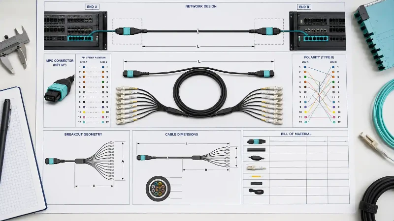
Turn the Network Drawing Into a Manufacturable Cable Specification
The most expensive MPO errors often begin before production. A purchase order may say "MPO-16, OM4, 10 m" while leaving out the pin arrangement, polarity, jacket requirement, breakout structure or labeling convention. A factory can manufacture exactly what is written and still deliver something that does not fit the channel.
A better RFQ starts from the two ends of the link and works inward.
Define End A and End B Separately
For each end, identify the equipment or panel interface, connector format, pinned or unpinned configuration, key orientation where applicable, end-face requirement and whether the cable connects directly to equipment or through an adapter or cassette. Do not assume both ends are identical.
Separate Connector Fiber Count From Total Cable Fiber Count
A high-fiber-count trunk can contain several MPO connectors. The connector fiber count and the assembly fiber count are different BOM fields. Keeping them separate is especially important when a project uses multiple MPO-12, MPO-16 or MPO-24 interfaces inside one trunk.
Freeze the Fiber Map Before the Cable Length
For a straight trunk, the mapping may be simple. For a fan-out or breakout assembly, every fiber position has to terminate at the intended destination leg. That map should be approved before production drawings are released. A polarity tester can confirm what was built, but it cannot decide what the project intended.
If the network is moving toward 400G or 800G and the optical interface is still being finalized, refer to the separate discussions on ribbon-structured MPO connectivity for 400G/800G and the 800G MPO-16 design considerations. The cable manufacturer should receive the final transceiver and lane requirements, not just the nominal Ethernet speed.
Design the Cable Around the Installation, Not Only the Optical Port
Once the optical mapping is clear, cable construction becomes the next design layer. This is where an optical cable manufacturer can add value that a connector-only specification cannot capture.
Choose the Fiber and Cable Structure Together
OS2, OM3, OM4 and OM5 identify optical fiber categories, but a finished MPO assembly also needs a physical cable construction. The correct design depends on whether the assembly is routed inside a rack, through an overhead pathway, between cabinets, through a conduit or into a harsher industrial environment.
Compact indoor patching may prioritize flexibility and small outer diameter. A permanent trunk may prioritize tensile protection, organized fiber grouping and installation protection. An industrial or outdoor transition may require additional mechanical or environmental protection. Hengtong's custom fiber optic cable engineering resources show how jacket materials, reinforcement, ribbon structures and environmental requirements affect the finished cable rather than only the glass inside it.
Specify Jacket and Fire Performance by the Actual Pathway
LSZH, PVC, riser-rated and other jacket requirements should come from the installation environment and applicable project code. A cable that performs optically can still be the wrong product if its jacket is not suitable for the building pathway or customer safety specification.
Do Not Treat Length as a Single Number
For a direct jumper, overall length may be enough. A trunk or breakout assembly can require several additional dimensions:
- overall cable length;
- breakout or fan-out length at End A and End B;
- distance from the jacket transition to the connector;
- branch-length differences where ports are staggered;
- length tolerance;
- pulling eye or installation protection, if required.
These dimensions should follow the rack layout. Standardizing every leg to the same length may simplify the purchase order but create unnecessary slack and poor cable management in the cabinet.
The Connector Termination Process Determines Whether Density Becomes Reliability
MPO technology places multiple fiber channels in one MT ferrule. That density is useful only when fiber positioning, guide-pin alignment, adhesive control, polishing and end-face cleanliness are repeatable.
The IEC 61754-7 family defines MPO interface dimensions for different ferrule arrangements, including IEC 61754-7-1 for single-row configurations and IEC 61754-7-3 for the two-row 16-fiber-wide interface. For the buyer, standards compliance is the baseline; consistent termination is what turns that interface into a production-ready cable assembly.
Ferrule Preparation and Fiber Placement
The fibers must be correctly sequenced and positioned in the ferrule before curing. On a multi-fiber assembly, a mapping mistake is multiplied across several channels at once. Production documentation should therefore tie fiber color or position to the approved polarity map.
Polishing and End-Face Geometry
Polishing removes excess adhesive and creates the final contact geometry. The goal is not simply a visually smooth ferrule. Fiber height, end-face geometry and surface condition influence physical contact and optical performance across the array. For high-volume production, repeatability is more valuable than a single "best" sample.
Cleanliness Is a Production Variable, Not Only a Field Issue
IEC 61300-3-35:2022 provides procedures for observing and classifying connector end-face defects and contamination. Multi-fiber connectors make inspection especially important because one contaminated ferrule can affect several fibers. Factory inspection and protective packaging should therefore be considered part of the manufacturing process, not an optional final check.
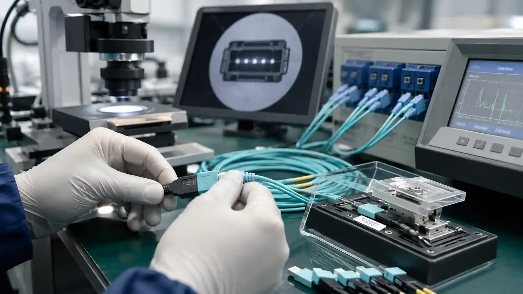
Factory Testing Should Match the Questions the Installer Will Ask
A useful factory test report does more than show that light passed through the cable. It should confirm that the assembly built on the production line is the same assembly that was approved in the project drawing.
At Hengtong, our MPO/MTP product line is 100% tested in production. For project orders, the test and documentation package can be aligned with the customer's acceptance requirements.
| Factory check | What it verifies | Typical project value |
|---|---|---|
| Insertion loss | Loss through each fiber path or connector interface | Confirms the assembly stays within the approved optical limit |
| Return loss / reflectance where specified | Back-reflected optical power | Important where reflection performance is part of the interface requirement |
| Polarity and fiber mapping | End-to-end position continuity | Confirms every fiber reaches the intended destination |
| End-face inspection | Contamination, scratches and defects | Reduces first-day failures caused by a dirty array interface |
| Visual and dimensional inspection | Length, branches, labels, boots and cable condition | Confirms the physical build matches the drawing |
| Serial / lot traceability | Relationship between product, test record and production batch | Supports commissioning, replacement and quality investigation |
For broader optical acceptance methods, Hengtong's fiber optic cable testing guide covers end-face inspection, OLTS loss measurement, OTDR analysis and documentation. For installed MPO-terminated cabling, IEC 61280-4-5:2020 specifically addresses attenuation measurement, polarity and length using test equipment with MPO interfaces. The central B2B principle is simple: agree on the test deliverables before production, not after the goods are packed.
The Assembly Type Changes the Manufacturing Risk
"MPO cable" is not one product category. Different assembly types create different manufacturing and installation risks.
| Assembly type | Typical B2B use | Manufacturing details to control |
|---|---|---|
| MPO-to-MPO jumper | Direct equipment links and short patching | Interface compatibility, polarity, bend protection and exact length |
| Multi-MPO trunk | Permanent high-density backbone between panels or cabinet zones | Total fiber count, connector grouping, pulling protection, labels and packing by route |
| MPO-to-LC breakout | Parallel-to-duplex conversion and port fan-out | Fiber-to-leg mapping, branch length, leg labels and connector sequence |
| MPO-to-MPO breakout | Splitting one higher-fiber-count path into several parallel interfaces | Position mapping, branch protection and destination identification |
| Ruggedized or waterproof MPO assembly | Outdoor cabinets, industrial connections and protected equipment interfaces | Sealing structure, mechanical protection and environment-specific cable construction |
For example, an MPO 1-to-N breakout assembly requires more than the correct connector count: each branch must be mapped, labeled and physically dimensioned for its destination. That is why a drawing is often more reliable than a one-line product description for custom orders.
What Professional Buyers Should Compare Between MPO Cable Manufacturers
Unit price matters, but it should not be the only comparison point. For project procurement, the lowest initial cable price can be outweighed by rework, installation delays, mislabeling or inconsistent replacement parts.
1. Can the Supplier Review the Specification Before Quoting?
A capable supplier should be able to identify missing fields such as polarity, pin configuration, branch length, jacket rating or test requirements before production starts. This does not replace the customer's engineering responsibility, but it helps prevent incomplete RFQs from becoming factory assumptions.
2. Can the Supplier Build the Same Approved Sample at Production Volume?
Sample performance matters only if it can be repeated. For bulk MPO procurement, ask how the approved drawing, materials, connector grade, labels and acceptance criteria are controlled when the order moves from sample to production.
3. Are Test Records Connected to the Product?
A spreadsheet with generic pass values is less useful than traceable records linked to cable IDs, batches or serialized labels. Traceability becomes especially important when hundreds or thousands of similar assemblies are installed across racks.
4. Can Packaging Follow the Installation Sequence?
Large data center projects may benefit from packing by rack, row, zone or route instead of by SKU alone. Clear packaging reduces sorting work on site and helps prevent the correct cable from being installed in the wrong location.
5. Can Future Replacement Orders Reproduce the Original Build?
A B2B cable program should consider spare parts and later expansion. Retaining approved drawings, part numbers, fiber maps and labels makes replacement easier than reverse-engineering an installed cable years later.
Common MPO Procurement Problems That Should Be Solved Before Production
- The RFQ names only the data rate. "400G MPO" or "800G MPO" does not fully define the physical interface or cable construction.
- The BOM mixes connector fiber count and trunk fiber count. This creates confusion about how many MPO interfaces are required on each end.
- Polarity is selected after the trunk is ordered. Polarity has to match the complete channel, not one cable in isolation.
- Branch lengths are copied from a previous project. The new rack layout may place ports differently.
- The cable jacket is chosen from a catalog default. The pathway or local safety requirement may require another material or rating.
- Labels are treated as cosmetic. In a dense patch field, poor identification becomes an installation and maintenance cost.
- Test reports are requested after shipment. Define data format and traceability before production begins.
- Sample approval covers performance but not packaging. For large orders, carton grouping and route identification can affect installation efficiency as much as the cable itself.
Where Custom MPO Cable Assemblies Add the Most Value
Standard jumpers are suitable when both equipment and routing are standard. Custom manufacturing becomes more useful when the project has many ports, repeated rack layouts, non-standard branch lengths, strict loss budgets, special labels, environmental requirements or deployment deadlines that make field rework expensive.
Data Centers and AI/HPC Clusters
High port counts make consistency critical. Pre-terminated trunks and breakout assemblies can reduce field termination work, but they also increase the value of correct polarity, route labels and factory verification. Hengtong's data center connectivity solutions provide the broader context for integrating MPO assemblies with the rest of the fiber infrastructure.
OEM and Equipment Integration
Equipment manufacturers may need repeatable cable lengths, controlled bend behavior, custom labels, specific connector orientations or packaging aligned to an assembly line. In this case, drawing control and production consistency may matter more than offering many catalog variants.
Telecom and Industrial Deployment
Where MPO is used outside a protected data hall, the cable and housing may need additional mechanical or environmental protection. Ruggedized and waterproof designs should be specified as complete assemblies rather than assuming a standard indoor jumper can be adapted in the field.
Frequently Asked Questions for B2B MPO Cable Buyers
What information is required for a custom MPO cable quotation?
At minimum, provide the connector configuration at both ends, fiber type, total fiber count, polarity or fiber map, length, cable construction, jacket requirement, quantity and test requirements. For breakout assemblies, include branch count, branch lengths and destination labels.
Should I send the transceiver model to the cable manufacturer?
Yes, when possible. The transceiver or equipment interface helps confirm the required connector presentation and active fiber positions. It is more reliable than specifying only the network speed.
Can a manufacturer customize labels and packaging for a project?
Project-specific labels and packing requirements should be included in the RFQ and approved with the drawing. This can be particularly useful when assemblies need to be distributed by rack, row or installation zone.
What should be included in an MPO factory test report?
The exact report depends on the purchase specification, but common checks include insertion loss, polarity or fiber mapping, end-face condition and product identification. Return loss or other measurements can be included when required by the project.
Why approve a sample before a large MPO order?
A sample gives the customer and manufacturer a physical reference for connector configuration, cable construction, dimensions, labels, optical performance and packaging. The approved sample and drawing can then become the reference for production.
Is low insertion loss the only sign of a good MPO cable assembly?
No. Optical loss is important, but a production-ready assembly must also have correct fiber mapping, suitable end-face condition, mechanical integrity, accurate length and labeling, and repeatable documentation. A cable that tests well but is mapped or labeled incorrectly can still fail the project.