

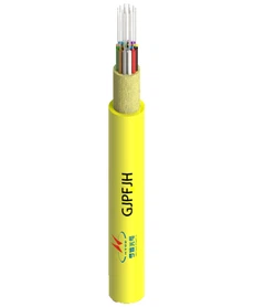



Sometimes, but a passing fiber optic cable duct fill ratio does not mean another cable can be installed safely. Calculate the space already occupied, then check whether the route provides a usable installation path. An existing cable, tight bends, damaged duct sections or excessive pulling tension can prevent an additional installation even when the calculated area fill looks acceptable.
For an occupied conduit, the practical decision is whether to use a vacant innerduct, assess a separate pathway, replace an existing cable with a higher-fiber-count design or investigate a carefully engineered alternative. The cable diameter matters, but so do the condition of the route and the method used to install it.

How Much Space Is Left in the Existing Duct?
For round cables inside a round conduit, calculate the area occupied by the existing cables and the proposed addition using the conduit's actual internal diameter. Do not substitute its nominal trade size. Conduits with the same nominal designation can have different internal dimensions depending on their sizing system, wall thickness and product specification. ASTM F2160 covers dimensional and performance requirements for solid-wall HDPE conduit used to protect telecommunications and other cables.
Area fill (%) = [(d1² + d2² + ... + dn²) / D²] × 100
Here, D is the conduit internal diameter and d1, d2 ... dn are the outside diameters of all the cables in the same internal space. The factor π/4 cancels from the numerator and denominator. Use the largest applicable outside diameter when checking a proposed cable against a project limit or installation allowance.
Calculate the current area fill first, then repeat the calculation with the additional cable included. The difference shows how much more of the theoretical cross-sectional area would be occupied. It does not describe the shape or continuity of the space between cables, particularly around bends and joints.
Worked Example: Adding a 12-Fiber Cable to an Occupied Duct
Consider a surveyed HDPE duct with a verified 41.15 mm internal diameter. It contains one existing cable with a 26.67 mm outside diameter. A proposed 12-fiber cable has an assumed outside diameter of 10.5 mm. These dimensions are illustrative inputs, not universal specifications for a 2-inch SDR11 duct or a 12-fiber cable.
| Item | Input or calculation | Result |
|---|---|---|
| Existing duct internal diameter | D = 41.15 mm | Internal area ≈ 1,329.9 mm² |
| Existing cable | d1 = 26.67 mm | Area ≈ 558.6 mm² |
| Current area fill | (26.67² / 41.15²) × 100 | 42.0% |
| Proposed additional cable | d2 = 10.5 mm | Area ≈ 86.6 mm² |
| Combined area fill | [(26.67² + 10.5²) / 41.15²] × 100 | 48.5% |

With both cables installed, the calculated occupied area would be about 48.5% of the conduit cross-section, leaving about 51.5% as a mathematical area remainder. That remainder is not necessarily a continuous opening large enough for a second cable to pass along the full route.
The next question is not whether 48.5% is below a convenient industry percentage. It is whether the applicable project requirements permit that arrangement and whether a safe installation method exists alongside the live cable. The underground conduit configuration also matters: one open duct, a subdivided duct and a bundle of separate microducts present different installation conditions.
Why a Passing Fill Calculation Is Not Enough
In a straight, empty conduit, the cable can occupy much of the available space without encountering another jacket. An occupied route is different. The existing cable may lie against the duct wall, change position through successive bends, or pass over joints and deformed sections. A new cable has to find a continuous route through these obstructions.
Several conditions can make a proposed addition unsuitable:
- Bends and sweeps: Friction and sidewall pressure increase through changes in direction; a gap visible at one access point may not remain open through a bend.
- Existing cable condition: Jacket damage, deformation or unknown installation history increases the risk of harming a working service during a second pull.
- Route condition: Ovality, collapsed sections, silt, debris, joint lips and inaccessible chambers can restrict the available passage.
- Mechanical limits: Installation tension, minimum bend radius, crush resistance and the cable's approved pulling arrangement must be checked against its own datasheet.
- Access and continuity: A duct may have sufficient area but no practical way to place pulling equipment, control tension or protect the existing cable.
The Fiber Optic Association's outside-plant installation guidance explains why innerducts are used to separate cables and why pulling additional cable into a conduit that already contains cables can lead to tangling, higher tension and damage. A suitable lubricant or a shorter pull does not, by itself, resolve an unprotected shared-path problem.
Before selecting a new cable, survey the entire route, check the as-built drawings against site conditions and obtain an installation method accepted by the pathway owner and qualified contractor. For a live network, plan how the existing service will be protected and monitored.
Three Retrofit Conditions That Require Different Decisions
1. An Existing Conduit Contains an Empty, Separate Microduct
An unused microduct offers a distinct installation path rather than requiring the new cable to rub against an existing one. Confirm its actual internal diameter, end-to-end continuity, joints, bends and condition before choosing a cable.
For air-assisted installation, the microduct must also be suitable for the equipment and proposed cable combination. Follow the duct supplier's cleaning, proving and leak-testing procedures where applicable. Do not assume an apparently unused microduct is unobstructed or pressure-tight.
2. The Main Conduit Is Occupied and Has No Separate Pathway
This is the more difficult retrofit. Even a moderate calculated fiber optic conduit fill ratio does not justify pulling a second cable directly past an installed cable. A new pull can disturb the original jacket, increase tension at bends or become trapped where cables cross.
Start with the condition of the existing route and consider whether a separate innerduct or other approved protective pathway can be installed without damaging the current cable. If separation is not feasible, compare replacing the existing cable with a higher-capacity design against establishing another route. Do not treat the addition of lubricant as approval for an otherwise unverified pull.
3. A Microduct Already Contains a Cable
An occupied microduct is not equivalent to an empty microduct with unused capacity. Introducing a second cable may interfere with the airflow, clearance and movement of the first cable. Standard single-cable jetting assumptions cannot simply be reused.
Do not plan a second blow into the same occupied microduct unless the system supplier and installation contractor have an approved method for that exact configuration. A vacant adjacent microduct, cable replacement or a separate route is generally a clearer starting point for evaluation.

Area Fill Ratio vs. Microduct Diameter Ratio
The term fill ratio is used for two different calculations. Confusing them can lead to an unsuitable cable-and-duct combination.
| Calculation | What it measures | Typical application |
|---|---|---|
| Area fill: Σd² / D² × 100 | Combined cable cross-sectional area relative to the conduit bore | Assessment of cables sharing a larger conduit or raceway |
| Diameter ratio: d / D × 100 | Outside diameter of one proposed cable relative to microduct internal diameter | Initial sizing of a cable for a specified microduct jetting system |
For example, an 8.5 mm cable in a 10 mm-ID empty microduct has an 85% diameter ratio; a 6.5 mm cable in the same microduct has a 65% ratio. Those figures identify two different clearances. They do not establish that the first cable will jam or that the second will travel a particular distance.
Even for a single cable, the ratios are numerically different: an 8 mm cable in a 10 mm-ID duct gives an 80% diameter ratio but a 64% area ratio. Neither should be compared directly against an unrelated percentage from a multi-cable conduit design table.
Microduct system qualification includes the cable, duct and installation method, not the diameter ratio alone. IEC 60794-5-10 is a family specification for outdoor microduct optical-fibre cables and associated ducts designed for installation by blowing. Suitable diameter ranges and expected installation performance must be confirmed for the selected products and equipment; they are not universal pass/fail limits.
Actual jetting performance also depends on route length, bends, cable mass and stiffness, jacket friction, duct internal condition, air supply and the jetting machine. A ratio within a supplier's preferred range is a reason to continue the engineering assessment, not a prediction of successful installation over 1,500 m or any other fixed distance.

Which Cable Structure Fits the Available Pathway?
A smaller cable diameter can increase the number of fibres available within a duct system, but only if the cable is approved for the intended installation method and operating conditions. Fibre count alone does not define cable outside diameter. Compare actual construction, maximum specified OD, mechanical limits and the installation method before ordering.
Conventional Duct Cable for an Approved Pulling Route
Where a separate duct or an otherwise approved pulling arrangement is available, a duct fiber optic cable can be assessed for the route's required fibre count, outside diameter, allowable installation tension, bending radius and protection needs. Different loose-tube, strength-member and sheath constructions do not share one universal pulling rating.
A conventional duct cable should not be selected merely because its cross-sectional area fits beside a live cable. The route must first support the proposed installation.
Stranded Loose-Tube Micro Cable for an Empty Microduct
For a suitable vacant microduct with greater fibre-count requirements, Hengtong's stranded loose-tube micro air-blown cable (GYCFHTY) is one option to evaluate. Its published typical outside diameters are 5.5 mm for 2–72 fibres, 6.2 mm for 74–96 fibres and 8.0 mm for 98–144 fibres.
These are product-family reference values, not the maximum permitted diameter of every ordered variant. Check the ordered design, fibre count, route conditions and microduct compatibility before estimating installation distance.
Center-Tube Micro Cable for Lower Fibre Counts
For lower fibre-count access routes, Hengtong's center-tube micro air-blown cable (GCYFXTY) lists typical diameters of 3.8 mm for 2–12 fibres and 4.1 mm for 14–24 fibres. Its compact construction may suit a smaller vacant microduct when the complete cable-and-duct pairing meets the project requirements.
A compact air-blown cable is not automatically a substitute for a cable specified for conventional winch pulling. Compare the mechanical ratings and approved installation method rather than using outside diameter as the only selection criterion.
Can Another Cable Be Installed? A Retrofit Decision Matrix
The calculation and field survey should guide the next engineering action, not serve as permission to begin pulling.
| Existing pathway | What the calculation can tell you | What must be verified | Next engineering action |
|---|---|---|---|
| Vacant, separate microduct | Candidate cable-to-duct diameter ratio | Actual bore, continuity, bends, duct condition and jetting-system compatibility | Qualify the selected cable/duct combination for air-assisted installation |
| Occupied main conduit, no separate innerduct | Current and proposed combined area fill | Safe continuous path, live-cable protection, allowable tension and access points | Assess an approved protected route, replacement design or alternative pathway |
| Occupied conduit with a documented spare innerduct | Capacity of the spare innerduct, calculated independently | Innerduct condition and appropriate cable installation method | Design the installation within the separate pathway |
| Microduct already containing a cable | Remaining cross-sectional area only | Whether an approved multi-cable installation system exists | Prefer an unused microduct or assess replacement unless the supplier approves another method |
| Deformed, obstructed or undocumented route | Dimensions may be unreliable | Actual bore and route condition after survey or remedial work | Resolve route uncertainty before selecting a cable or approving installation |
There is no single 55% or 70% area-fill threshold that approves or forbids every existing fibre conduit retrofit. Some electrical raceway rules and supplier calculation tools use particular fill limits, but their scope, installation assumptions and local applicability must be checked rather than transferred to unrelated underground telecom ducts.
What to Confirm Before Ordering Additional Fiber Cable
The cable supplier and installation contractor need enough site information to select a workable design. A request for "12-core cable small enough for a 2-inch duct" leaves several critical details unanswered.
- Pathway: duct material, dimensional specification, verified internal diameter, existing innerducts and available spare pathways.
- Existing installation: number of installed cables, measured or documented outside diameters, cable condition and whether the service must remain live.
- Route geometry: total length, intermediate access points, bends, sweep radii, joint locations and any known restrictions.
- New capacity: fibre count required now, expected future demand, fibre type and any specified protection or water-blocking requirements.
- Candidate cable: construction, nominal and maximum outside diameter, weight, minimum bend radius, approved pulling or blowing method and mechanical limits.
- Installation plan: contractor's pathway assessment, tension-control method or approved jetting-system settings, and measures to protect existing traffic.
- Qualification: required inspection records, baseline optical measurements, final acceptance criteria and responsibility for any remedial work.
After installation, compare route condition and fibre performance against agreed acceptance criteria. Depending on the project, this includes continuity, attenuation and OTDR records. The test sequence and documentation can be aligned with the site's fiber optic cable acceptance testing requirements, particularly where an existing live cable may have been disturbed during construction.
Frequently Asked Questions
Can you pull another fiber cable through a conduit that already has one?
Do not assume so. A second cable needs an approved installation route that protects the existing cable. Area fill is only an initial sizing calculation; the pathway configuration and pulling method must also be assessed.
Does a 40% duct fill ratio mean a new cable will fit?
No. An area-fill percentage does not reveal whether there is a continuous passage through bends, damaged duct sections or existing cables. Any applicable fill rules also depend on the governing standard and installation conditions.
Can two micro cables be blown into one occupied microduct?
Not on the basis of a single-cable diameter ratio. Adding a cable to an occupied microduct requires an explicitly approved cable, duct and installation arrangement. A separate empty microduct is normally the simpler candidate to investigate.
Is replacing the existing cable sometimes better than adding a second?
Yes. If there is no safe separate pathway, replacing an older cable with an appropriately specified higher-fibre-count cable may be more practical than attempting a second pull. The decision must account for service interruption, restoration work, capacity needs and route access.
Conclusion
Start with the actual duct internal diameter and the outside diameters of every installed and proposed cable. Calculate the combined fiber optic cable duct fill ratio, then verify that the route provides a safe installation path. In an occupied conduit, that second step often determines the project outcome.
A vacant microduct may support a suitably qualified air-blown cable. A conduit occupied without protective separation requires a different assessment. Where no workable path remains, replacing a cable or providing another duct may be the sounder option. Confirm the route and the installation method before choosing the cable diameter or ordering additional fibre capacity.