




Yes, some expanded beam optical (EBO) connectors can be installed in existing MPO panels or adapters. That does not mean they can mate optically with conventional physical-contact MPO connectors. A successful retrofit depends on three separate checks: whether the hardware fits, whether the two connector ends are an approved optical mating pair, and whether the finished channel meets its loss and test requirements.
For a data center with installed MPO trunks, this distinction determines what can stay in service. The panel may be reusable while the adapter or patch cords need replacement. In other cases, an EBO connector fits the installed adapter, but only when another compatible EBO connector is fitted on the opposite side. The objective is to preserve working cabling where possible, not to replace every MPO connection simply because a new connector technology is available.

Expanded Beam vs Conventional MPO: What Actually Changes?
MPO is a multi-fiber connector interface. Conventional MPO/MTP connections use accurately aligned, polished multi-fiber ferrules that are brought into physical contact when mated. Expanded beam describes a different optical coupling method: lenses expand and collimate light from the transmitting fibers, carry it across a controlled gap, and focus it into the receiving fibers. The opposing optical surfaces do not need to touch.
These descriptions are not mutually exclusive. An expanded beam connector may be built in an MPO-style housing. Its outside shape can look familiar while the optical interface inside is fundamentally different.
The IEC 61754-7-1 MPO interface specification addresses one-row configurations, while IEC 61754-7-2 covers two-row configurations. These standards define interface dimensions for their respective MPO variants; they should not be interpreted as a blanket guarantee that an arbitrary lensed ferrule and a physical-contact ferrule will transmit light when brought together.
Physical-contact connections can achieve very low loss when correctly assembled, inspected and mated. Expanded beam designs can make localized contamination less disruptive because the optical beam occupies a larger area at the interface. Neither statement tells an engineer whether a particular pair of connectors is acceptable. That requires product-specific drawings and optical data.
Three Different Meanings of MPO Compatibility
1. The Adapter Fits the Existing Panel
An EBO adapter may have an MPO-compatible mounting footprint. This means its housing can fit the opening or retaining arrangement in an existing patch panel. The metal panel can remain, but the original MPO adapter might still need to be removed.
Panel drawings matter here. Compare the cutout, flange, retaining clips, adapter orientation, rear clearance and the space needed to reach densely populated ports. A familiar rectangular footprint is not enough to establish a reliable installation. Existing MPO/MTP adapter-panel installation arrangements can also affect access to keys and latches once a panel is fully populated.
2. The Connector Fits the Existing Adapter
Some EBO connectors are designed for particular standard MPO adapters or compatible adapter families. In this case, technicians may be able to keep the adapter as well as the panel. Other designs use a dedicated adapter to provide alignment or retention and cannot be substituted into the existing sleeve.
Confirm the exact adapter and connector part numbers. Check key orientation, latch engagement, alignment features and manufacturer restrictions. Do not assume that all adapters carrying an MPO designation are suitable for every MPO-form-factor expanded beam product.
3. The Two Ferrules Are Approved to Mate Optically
This is the decisive test. An EBO connector that locks into an MPO adapter may still be unable to form an optical connection with the physical-contact MT ferrule on the other side. Unapproved mating can produce unacceptable loss and may damage an interface, depending on its design.
The supplier should identify the approved mating partner, not merely the adapter style. For an EBO installation, both sides of the non-contact optical junction generally need to be part of a compatible expanded beam system unless the manufacturer has expressly qualified a different arrangement. A component should never be described as a drop-in optical replacement on the strength of mechanical fit alone.

Compatibility Verification Matrix for an Existing MPO Network
Before ordering connectors, compare the planned EBO configuration with what is installed. The following matrix separates a product claim from the document or test result needed to support it.
| Check | What to verify | Evidence required |
|---|---|---|
| Connector and ferrule | Exact optical coupling type, ferrule design and intended mating arrangement | Current model drawing and optical interface description |
| Panel mounting | Cutout, flange, retention and service clearance | Dimensioned panel and adapter drawings |
| Adapter fit | Keying, latching and alignment of the proposed connector-adapter combination | Approved adapter part numbers |
| Optical intermateability | Exact connectors approved to form the mating pair | Manufacturer's written compatibility statement or qualification report |
| Fiber arrangement | Single-mode or multimode, fiber count, lane assignment and termination style | Assembly configuration and channel mapping |
| Polarity | End-to-end transmit/receive mapping across trunks and transitions | Verified polarity drawing and test record |
| Insertion loss | Specified maximum or distribution under defined conditions, not only a typical marketing value | Product datasheet and per-fiber measurement report |
| Return loss | Performance at the intended wavelength and mating configuration | Relevant RL data or test report |
| Inspection and acceptance | Lens-specific inspection, suitable reference cords and agreed measurement procedure | Manufacturer test instructions and project acceptance plan |
For polarity, do not infer the channel map from the connector's front view alone. Trunk wiring, key-up/key-down orientation, guide-pin arrangements and any transition assembly must be treated as one end-to-end optical path. The pin and alignment details of the selected EBO system may differ from those of the existing physical-contact hardware.
Can Existing MPO Trunks Stay in Place?
Often they can, provided the existing trunk is in suitable condition and its fiber type, count, polarity and remaining loss allowance match the new design. A partial retrofit typically changes a connection point, not necessarily the length of trunk cable behind it.
Example: Retaining an MPO Trunk but Changing a Cross-Connect
Consider a trunk ending in a conventional physical-contact MPO connector at a distribution panel. If the operator wants an EBO mating interface at the serviceable cross-connect, one possible arrangement is:
Existing MPO trunk → approved conventional MPO mating pair → transition assembly terminated with EBO → approved EBO mating pair → EBO-to-conventional transition assembly → existing equipment connection.
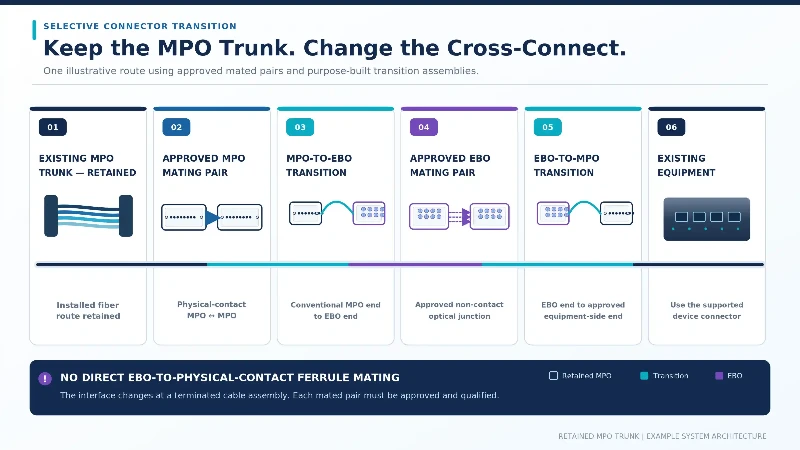
A transition assembly here means a fiber assembly with the appropriate, different connectors at its two ends. It does not mean that an EBO ferrule mates directly with a physical-contact MT ferrule. Every transition introduces physical connectors, cable length and potentially additional loss; the complete channel has to be re-budgeted and tested.
Where the trunk terminates at equipment using fixed MPO receptacles, retaining conventional MPO jumper connections at the equipment end may be more practical than replacing the entire interface system. A custom fiber optic cable assembly may provide an appropriate transition, but only after both optical ends and their mating partners have been specified and approved.
Conversely, a panel with many fixed, low-loss MPO connections that are rarely disturbed may gain little from an EBO conversion. Leaving those connections alone can be the lower-risk engineering choice.
How Expanded Beam Changes the Optical Loss Budget
Insertion loss must be evaluated per completed mating pair under the manufacturer's stated conditions. Do not compare the typical insertion loss of one EBO design with the guaranteed maximum of an unrelated physical-contact MPO product and call the difference an upgrade penalty. Fiber type, wavelength, test method, reference connector and sample distribution all affect the result.
Older ruggedized expanded beam designs and newer high-density lensed connectors may use different optical architectures. Their loss figures are not interchangeable. An air gap and lens surfaces also make return-loss behavior relevant, but they do not imply that every EBO connector has poor back-reflection performance. Use the specified performance of the actual ordered configuration.
Illustrative 50 m Link Budget
The following calculation keeps the structure of a typical retrofit estimate, but all numerical values are illustrative assumptions. They are not product guarantees or published limits for an EBO connector, an MPO connection or a particular transceiver.
Assume a 50 m single-mode channel at 1310 nm. The hypothetical transceiver has a minimum transmit power of −2.5 dBm and a receiver sensitivity of −6.5 dBm, giving an assumed 4.0 dB optical power budget. The channel has two conventional mated connections, one approved EBO mated connection and two fusion splices.
| Loss item | Assumption | Estimated loss |
|---|---|---|
| Fiber attenuation | 0.05 km × 0.40 dB/km | 0.02 dB |
| Conventional mated connections | 2 × 0.50 dB | 1.00 dB |
| Approved EBO mated connection | 1 × 0.70 dB | 0.70 dB |
| Fusion splices | 2 × 0.10 dB | 0.20 dB |
| Total estimated attenuation | 0.02 + 1.00 + 0.70 + 0.20 | 1.92 dB |
| Unallocated budget | 4.00 − 1.92 | 2.08 dB |

Under those assumptions, the preliminary calculation leaves 2.08 dB unallocated. That is not proof of a working channel. The design still needs the correct transceiver/PMD limits, appropriate worst-case connector allowances, aging and operating margins, valid mating arrangements, polarity verification and measured losses for every active fiber lane.
If a chosen EBO product specifies only a typical insertion loss, it cannot be inserted into a worst-case design budget as though it were a guaranteed maximum. Obtain the applicable maximum, qualification data or agreed acceptance distribution from the supplier. Recalculate the path if transition assemblies introduce more connection points than shown above.
Inspection and Testing After an MPO-to-EBO Transition
Inspection Is Not the Same as Optical Acceptance
The larger optical footprint of an expanded beam interface may reduce the effect of certain small localized contaminants. It does not cause light to travel around dirt, and it does not make lenses immune to fingerprints, oils, coating damage or misplaced particles. The supplier's inspection and cleaning procedure still matters, particularly after handling and repeated field mating.
Conventional MPO connections also benefit from controlled inspection and cleaning practices; the main practical issues and handling risks are already addressed in MPO jumper contamination protection. For the new EBO interface, apply the requirements appropriate to its lens design rather than reusing physical-contact pass/fail zones without review.
IEC 61300-3-35:2022 provides visual inspection criteria for fiber-optic connector end faces based on physical-contact optical interfaces. Its published scope also makes clear that a visual examination does not replace optical qualification such as attenuation and return-loss measurement. An EBO lens requires an inspection procedure and acceptance criteria applicable to that specific interface.
Measure the Finished Channel with an Appropriate Reference Setup
For installation acceptance, use a calibrated optical loss test arrangement with reference cords and mating fixtures appropriate to the interface under test. Record which connections are included or excluded by the reference method. A transition lead is not automatically invalid, but its loss and reference implications must be known and documented.
The IEC 61300-3-4:2023 attenuation test standard describes methods for measuring optical components. The method selected for a specific product or installed link must match the component type and project requirements; a standard number alone does not validate an improvised reference configuration.
Record channel losses by fiber number, at the relevant operating wavelength and in the designated direction or directions. Confirm connector return loss where it matters to the equipment, verify polarity, and repeat measurements after any required re-mating cycles. Compare the results with the agreed acceptance criteria and the actual transceiver channel budget-not a generic figure attached to the words "400G" or "800G."
Where OFDR Fits
High-resolution optical frequency domain reflectometry (OFDR) can help investigate closely spaced reflections and losses in complex connector structures, including lenses and short internal gaps. It is useful for engineering characterization or difficult fault diagnosis. It is not a universal requirement for every EBO panel installation, and a reflectometry trace should be interpreted using the actual component geometry rather than treating every unusual peak as a damaged connector.
Research coordinated by iNEMI on expanded beam and physical-contact connectors specifically examines contamination, insertion loss and return loss in data center conditions. Its existence reinforces the need to measure real operating behavior instead of assuming that every EBO design performs identically.
What Does the 2026 EBO MSA Mean for Interoperability?
The Expanded Beam Optics Multi-Source Agreement (EBO MSA) is working toward common specifications that can support a broader multi-vendor supply base. Its September 2026 updates show substantial industry participation, but its public website still directs visitors to a section where released specifications will appear.
A manufacturer's participation in a standards group is not a substitute for an approved connector pairing or an optical test report. Procurement teams should request the exact specification revision claimed by the product, along with any available cross-vendor intermateability evidence. Until those documents are available, the safe purchasing unit is the documented connector-and-mating-partner combination.
Industry adoption does not automatically resolve older MPO retrofit questions. Installed adapters vary, existing connectors may have different optical finishes and polarity arrangements, and a new non-contact interface still has to meet the system loss budget.
When Should Conventional MPO Be Retained?
| Site condition | Reasonable next step | Decision criterion |
|---|---|---|
| Stable, clean MPO patching with little reconfiguration | Retain physical-contact MPO | No proven operational benefit that justifies changing a working interface |
| High-traffic cross-connect exposed to frequent handling | Trial an approved EBO mating system at that point | Repeatable loss and handling performance under actual service conditions |
| Existing panel opening matches an EBO adapter footprint | Evaluate panel reuse | Dimensional fit, retention, access and approved connector pairing |
| Old MPO trunk must remain connected to conventional equipment | Specify qualified transition assemblies if needed | No direct incompatible mating; polarity and added loss verified |
| Channel budget has little remaining margin | Keep the lower-loss qualified arrangement or redesign | Worst-case loss allowance with operating reserve |
| Multiple EBO suppliers proposed | Check each claimed mating combination | Documented interoperability, not supplier membership alone |
Most existing networks can be assessed one connection at a time. A general MPO/MTP network upgrade may involve new trunks, cassettes or bandwidth planning. EBO integration poses a narrower question: is there a particular serviceable connection whose new optical interface delivers enough practical benefit to justify qualification and change control?
Procurement and Qualification Checklist
Before issuing a purchase order for an expanded beam retrofit, ask for the following documents and answers:
- Exact connector part numbers: identify fiber type, lane count, ferrule construction, keying and the approved optical mating partner.
- Mechanical drawings: compare the connector, adapter, panel opening and service clearance under the site's actual mounting conditions.
- Intermateability evidence: obtain written confirmation for the specified pair, including any restrictions on other manufacturers or product generations.
- Optical performance: request maximum insertion-loss requirements, return-loss data, test wavelength, sample conditions and repeat-mating results where relevant.
- Polarity documentation: map every lane across the retained trunk, each transition assembly and the final equipment port.
- Inspection and reference equipment: agree on lens handling, inspection criteria, mating fixtures and reference cords before field acceptance.
- Site acceptance plan: record per-lane losses, any required return-loss tests, the allowed project limits and the resolution of failed results.
- Spare parts and support: confirm replacement adapters, approved mating cords, documentation revisions and availability throughout the expected service life.
Existing MPO/MTP product ranges provide a useful baseline for recording the installed system's fiber count, termination style and assembly requirements. They should not be treated as evidence that any specific EBO component is already offered or qualified by the same supplier.
Frequently Asked Questions
Can an expanded beam connector plug into a standard MPO adapter?
Some models can, but only with the adapter families approved by their manufacturer. Mechanical insertion into an adapter does not establish an acceptable optical connection with the connector on the other side.
Can a physical-contact MPO connector mate directly with an EBO connector?
Do not assume so. Use only explicitly approved mating combinations. Many lensed non-contact interfaces require another compatible expanded beam interface rather than a conventional polished MT ferrule.
Do existing MPO trunks have to be replaced to use EBO?
Not necessarily. A suitable trunk may remain in place while the selected service connection changes through approved assemblies and adapters. The complete revised path, including every added mated pair, must still be qualified.
Is expanded beam always lower-maintenance and lower-loss than MPO?
No. Some EBO interfaces tolerate certain contaminants better, but inspection requirements and optical losses vary widely by design. Compare documented product performance and actual service conditions rather than treating one optical coupling method as universally superior.
Conclusion
Existing MPO panels may be reusable with expanded beam optical connectors, but panel fit, adapter fit and optical intermateability are separate approvals. For a practical retrofit, start with the installed connector and panel drawings, identify an approved EBO mating pair, account for any transition assemblies and calculate the resulting channel loss using the selected products' applicable performance limits. Then measure the finished link.
Conventional MPO remains a sound choice for stable, qualified connections. EBO deserves consideration where frequent handling or contamination makes a non-contact interface useful, provided that its optical performance, interoperability and operating requirements are demonstrated for the specific installation.