




Optical circuit switching (OCS) can change how an AI data center connects groups of computing equipment without sending every interconnection through another layer of electronic packet switches. It does not eliminate Ethernet, make network latency disappear, or remove the need for a carefully designed fiber plant. An OCS deployment still depends on physical fiber routes, compatible optical interfaces, a workable loss budget, and accurate port mapping.
Google's Jupiter network shows why operators are interested in the approach. The more immediate question for cabling engineers is what happens between the optical circuit switch, the transceivers, and the distribution panels when those light paths become reconfigurable.
What Is Optical Circuit Switching?
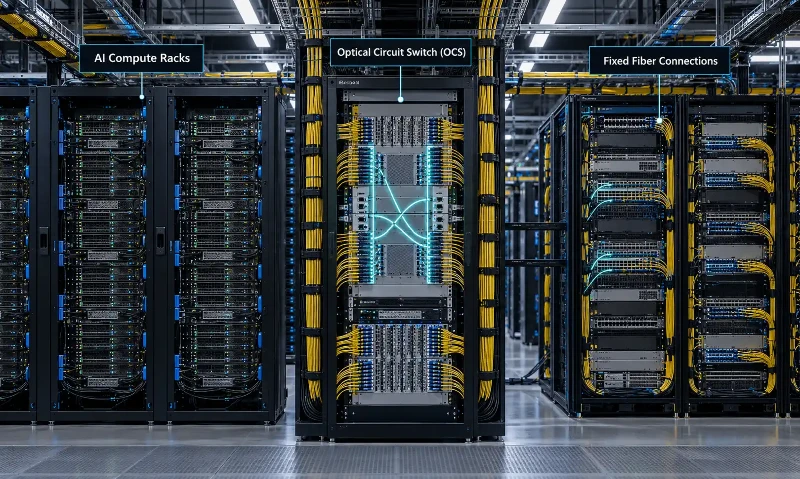
An optical circuit switch establishes a physical light path between selected optical ports. In a micro-electro-mechanical systems (MEMS) design, movable mirrors direct light from an input fiber toward a selected output fiber. Once the circuit is established, the switching element passes the optical signal without electronically examining or forwarding individual packets.
The control system decides which ports to connect. The data travels over the established optical path. Changing that path requires a new switch configuration, so circuit reconfiguration and packet forwarding are different operations with different time scales.
OCS is often described as transparent to the format of the optical signal. That describes the switching function, not unconditional compatibility with every transceiver. Supported wavelengths, optical power, fiber type, connector interfaces, polarization behavior, and allowable loss must still be checked against the specific system.
Optical Circuit Switching vs. Ethernet Packet Switching
Ethernet packet switches inspect forwarding information and direct traffic through electronic switching resources. An OCS connects physical optical paths. The two can operate in the same network: Ethernet handles packet forwarding while OCS changes which network blocks have direct optical connectivity.
| Design question | Ethernet packet switching | Optical circuit switching |
|---|---|---|
| What is switched? | Packets or frames within electronic switching hardware | Established optical paths between ports |
| How is traffic directed? | Forwarding tables and packet-processing functions | External control and optical-path configuration |
| How are traffic changes handled? | Packets can be forwarded as traffic patterns change | Connections are reconfigured when the topology needs to change |
| Is packet processing performed inside the switch? | Yes | No, not in the optical switching fabric |
| What must the engineer verify? | Electrical and optical interfaces, packet performance, forwarding behavior | Optical interfaces, port mapping, path-dependent loss, switching control and recovery |
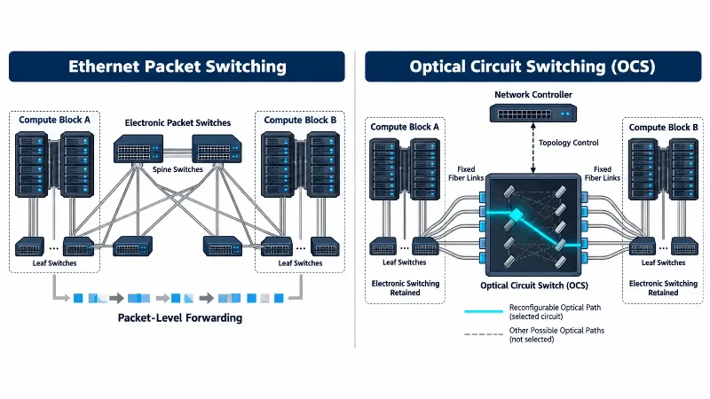
OCS therefore tends to be more useful when a network controller can identify traffic patterns that justify maintaining or reconfiguring particular connections. Short-lived or unpredictable flows may still need electronic packet switching. An OCS also introduces control-plane coordination and an interval during which a circuit is being changed; it cannot be treated as a zero-delay packet switch.
What Google's Jupiter Deployment Actually Demonstrates
Google's Jupiter system provides a documented production example, rather than a projection about an unspecified 100,000-GPU cluster. In the Jupiter Evolving paper presented at ACM SIGCOMM 2022, Google described moving from a conventional Clos-style fabric toward direct connections among machine-aggregation blocks, using MEMS-based OCS and software-defined networking to adjust the available topology.
The researchers reported a 30% reduction in network capital expenditure and a 41% reduction in power relative to the evaluated earlier approach. They also reported that about 60% of traffic between aggregation blocks took a direct path; that figure does not mean that OCS carried 60% of traffic between GPUs. These are results from Google's particular network evolution and comparison conditions, not guaranteed savings for every AI cluster.
Google later described a different OCS application in its TPU systems. Its March 2026 Ironwood technical overview explains how inter-chip interconnects, OCS, and the data center network contribute to a larger TPU system. Ironwood and the earlier Jupiter study should not be combined into a single cost benchmark: they describe different systems and objectives.
Both examples illustrate a broader point. Network designers may be able to change the pattern of optical connectivity without rebuilding the physical cabling every time traffic demand changes. That flexibility only works when the fixed fiber links and their port assignments are engineered correctly.
What Changes for the Fiber Plant?
1. Plan the fixed connections around a reconfigurable topology
The light path changes inside the OCS, but the cables from equipment to OCS ports remain physical assets. Their endpoints, routes, lengths, labeling, and accessible service locations must be documented. A logical connection drawn in network software is not evidence that the correct two fibers have been installed.
For larger facilities, the relevant scope can extend from inter-rack links to distribution points between data halls. These pathways need to be coordinated with the rest of the data center fiber infrastructure, rather than planned as an isolated set of OCS patch cords.
2. Confirm fiber type and reach before selecting cable
OCS does not specify a universal cable construction. The optical equipment determines whether the link uses single-mode or multimode fiber, which wavelengths are supported, and what transmission reach is practical. Where the design calls for single-mode optical fiber, fiber attenuation, bend performance, and the specified connector system need to be assessed together.
Fiber count is another design input, not a marketing target. The required number of circuits, whether each circuit is simplex or duplex, planned spare capacity, and any separate monitoring fibers should be agreed before the trunk is ordered. More installed fibers do not automatically mean more usable OCS circuits if the port mapping is wrong.
3. Treat connector selection as an interface decision
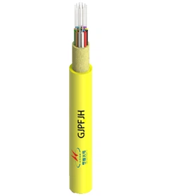
Pre-terminated fiber optic cable assemblies can simplify repeated equipment-to-panel connections, provided the assembly length, fiber type, connector gender, polishing requirement, and test specification match the design.
High-density MPO/MTP connectivity may be appropriate in portions of a parallel-optics or distribution-panel design. It should not be assumed to be the native interface on an OCS. Some equipment uses other multi-fiber or single-fiber connectors. Verify the actual port interface and approved mating arrangement before selecting harnesses, cassettes, or breakout assemblies.
In an OCS installation, cable-management quality also affects troubleshooting. A clearly labeled trunk and a consistent mapping between equipment ports, patch-panel ports, and OCS ports can be more useful during commissioning than simply minimizing the number of visible patch cords.
How Does OCS Affect the Optical Link Budget?
The optical circuit switch contributes insertion loss to the channel. The complete budget also includes optical fiber attenuation, connector and splice losses, and any other relevant passive components. The transceiver's supported optical budget sets the boundary; the OCS is not a source of additional optical power.
Estimated channel loss = fiber loss + connector loss + splice loss + OCS path loss + other applicable losses.
For equipment qualification, use the relevant maximum or specified worst-case losses rather than replacing them with typical laboratory values. Check whether a vendor's OCS insertion-loss figure already includes specific input/output connector interfaces; otherwise the same component could be counted twice.
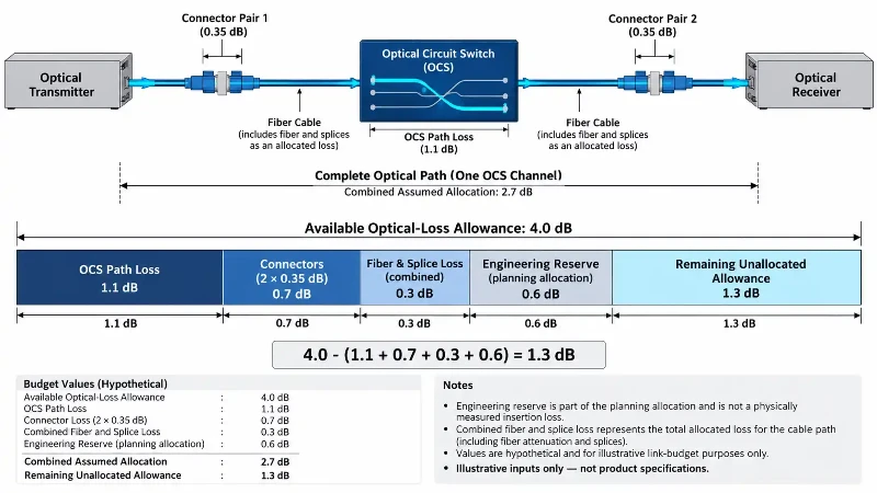
Illustrative calculation: one OCS channel
Consider the following hypothetical engineering inputs. They are provided solely to show the calculation and are not measurements or specifications for a Google deployment, an OCS product, or a Hengtong cable.
| Assumed budget item | Illustrative value |
|---|---|
| Available transceiver optical-loss allowance | 4.0 dB |
| One OCS path, assumed maximum loss | 1.1 dB |
| Two separate mated connector pairs, 0.35 dB each | 0.7 dB |
| Combined fiber and splice loss | 0.3 dB |
| Additional engineering reserve | 0.6 dB |
| Combined assumed allocation | 2.7 dB |
| Unallocated allowance | 1.3 dB |
The arithmetic is 4.0 - (1.1 + 0.7 + 0.3 + 0.6) = 1.3 dB. This does not certify a working link. The designer must replace every illustrative input with system-specific limits, verify wavelength and receiver operating conditions, account for additional penalties required by the transceiver specification, and test the actual route.
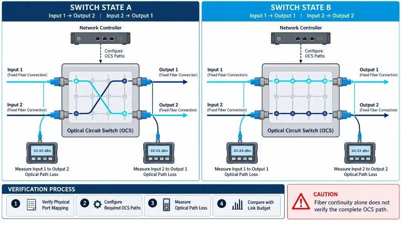
For a matrix switch, one measured input-to-output path may not represent every possible path. Qualification should consider the variation in insertion loss across relevant port combinations and the operating states the controller is expected to use.
Why OCS Fiber Connectivity Verification Is Different
When a conventional packet-switched network is active, operators can often use packet-based discovery and monitoring to understand how devices are connected. An OCS fabric does not inherently process those packets. A fiber that carries some light may still be connected to the wrong port or have too much loss to support its intended transceiver.
A June 2026 NTT Technical Review study of OCS network operations identifies two separate acceptance problems: determining whether the installed fiber topology matches the intended topology, and determining whether the optical loss on each link is acceptable. Its proposed verification methods use optical probing and received-power measurements to investigate these questions at scale.
Verify the path, not just continuity
- Check the port map: match the equipment port, intermediate panel, cable identifier, and OCS port against the approved connection schedule.
- Inspect and qualify the fiber connections: use an appropriate inspection and fiber optic cable testing procedure for the connector type and link configuration.
- Measure path loss: establish a suitable reference method and compare actual optical power or insertion loss with the allowable budget for that optical circuit.
- Exercise required switch states: verify the intended connectivity and optical performance across representative or specified OCS configurations, rather than only one static route.
- Record results: keep the port map, test conditions, measured results, and any corrected connections with the project handover documentation.
An optical time-domain reflectometer may help locate a fault in an accessible fiber span, but OTDR testing alone does not identify every controller-to-port mapping error or prove the full operational OCS channel meets the transceiver budget. The acceptance method must be appropriate for the installed configuration.
What Are the Limits of OCS in AI Data Centers?
OCS brings a different set of trade-offs from electronic switching. A circuit needs to be established before it can carry the intended traffic; changing connections introduces switching and control overhead. Applications with predictable, sustained communication patterns may make better use of a reconfigurable optical fabric than workloads that require rapid packet-level decisions across many destinations.
Deployment also adds requirements for controller integration, optical-port availability, fault handling, and spare-path planning. A failed component or incorrect fiber connection can affect whichever logical circuit is assigned to that physical path. Those operational costs belong in a comparison with an all-electronic alternative, alongside equipment cost and power consumption.
Industry work is continuing rather than being settled by one manufacturer's deployment. The Open Compute Project's OCS subproject is working on open hardware and software specifications, interoperability, and telemetry. Participation in a standards project should not be confused with proof that every participant has deployed an identical OCS system in production.
Frequently Asked Questions
Does optical circuit switching replace Ethernet switches?
Not generally. OCS can provide reconfigurable optical connectivity between selected network blocks, while Ethernet packet switches remain responsible for packet forwarding and many other networking functions. The balance depends on the architecture.
Is optical circuit switching faster than Ethernet?
They perform different functions. OCS can pass an established optical signal without per-packet electronic switching inside the optical fabric, but establishing or changing a circuit takes time. End-to-end latency also depends on transceivers, fiber distance, controllers, and any packet switches elsewhere in the path.
Does an OCS system require MPO/MTP cables?
No universal connector type is required by the concept of OCS. The port interfaces and approved cable assemblies are determined by the selected equipment and its optical architecture. MPO/MTP may be useful for parts of a high-density fiber distribution system without being the OCS's native connector.
Can a normal fiber continuity test qualify an OCS network?
No. Continuity alone does not establish correct endpoint mapping or acceptable loss across the required OCS configurations. The verification plan should test both the physical topology and optical performance against the equipment's limits.
Conclusion
Optical circuit switching offers a way to reconfigure portions of an AI data center's optical connectivity without performing packet switching at every interconnection point. Google's Jupiter work demonstrates that such an architecture can deliver meaningful benefits under specific operating conditions, but those results are not universal cost or performance guarantees.
For the fiber plant, the practical work remains concrete: specify compatible interfaces, document every physical route, calculate the complete optical budget, and prove the installed connections match the intended topology. Those checks determine whether a reconfigurable optical network can be operated reliably after the cabling is in place.