






Narrower than most explanations suggest. A polarization-maintaining fiber (PM fiber, or PMF) does not freeze whatever polarization state you feed into it. It preserves a linear polarization that has been launched aligned to one of its two eigenaxes - the slow axis or the fast axis. Get the launch alignment right and the output state stays stable across bending, handling and temperature. Get it wrong and the fiber carries two components that beat against each other, and the output polarization drifts much as it would in ordinary fiber.
That limitation is exactly why PM fiber has become a talking point in co-packaged optics (CPO). In CPO designs that place the laser outside the switch package, the fiber between the laser module and the silicon photonics engine has to deliver light in a known, stable polarization state - because the couplers and modulators waiting at the far end only work properly for one of them.
What Polarization-Maintaining Fiber Actually Maintains
Light is an electromagnetic wave, and the orientation of its electric field is its polarization. In a standard single-mode fiber, two orthogonal polarization modes travel with almost the same propagation constant. "Almost" is the problem: core ellipticity from the draw process, residual stress, bending, twisting, side pressure and temperature all introduce small, uncontrolled amounts of birefringence. Power leaks continuously between the two modes, so the output polarization wanders and depends on how the cable happens to be routed that day. This same mechanism, at a different timescale, is what shows up in long-haul links as polarization mode dispersion.
PM fiber attacks the problem by making the birefringence large and deliberate instead of small and random. Two orthogonal axes are defined by design, with a refractive index difference typically in the range of a few times 10-4 for telecom-wavelength PM fiber. The axis with the higher index is the slow axis; the other is the fast axis. Because the two modes now travel at appreciably different phase velocities, external perturbations no longer have enough phase-matching to transfer power efficiently between them. Coupling is suppressed, not eliminated.
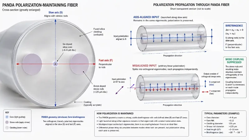
Two consequences follow, and both matter in practice:
- The fiber maintains a state only if that state was linear and aligned to an eigenaxis at launch. Feed in circular or arbitrary elliptical light and PM fiber gives you no benefit at all.
- Because the two modes accumulate phase difference, the relative phase repeats over a characteristic distance called the beat length (LB = λ/Δn), which is on the order of a few millimetres at 1550 nm for typical PANDA fiber. Short beat length means strong birefringence and better resistance to mode coupling.
How the Birefringence Is Built In
There is more than one way to create the two axes, and PANDA is one design among several rather than a category name:
- PANDA - two circular boron-doped stress rods on either side of the core. Widely used, and the design most people picture. Corning, which invented and patented the PANDA structure, offers it across wavelengths from roughly 400 nm to 1550 nm.
- Bow-tie - wedge-shaped stress regions, generally giving higher birefringence at the cost of process complexity.
- Elliptical stress cladding - an asymmetric stress layer surrounding the core.
- Elliptical core - geometric rather than stress-induced birefringence.
- Photonic crystal / microstructured - birefringence from an asymmetric air-hole lattice.
Stress-based designs work through differential thermal contraction: the doped regions shrink more than the surrounding silica as the fiber cools after drawing, and the resulting anisotropic stress produces the index difference through the photoelastic effect.
Standard Single-Mode Fiber vs PM Fiber
| Property | Standard single-mode fiber | PM fiber |
|---|---|---|
| Internal birefringence | Low and uncontrolled | High and deliberately engineered |
| Polarization axes | Not defined; output state drifts | Defined slow axis and fast axis |
| Launch requirement | No axis alignment needed | Linear input must be aligned to an eigenaxis |
| Connector and splice work | Rotationally symmetric | Requires angular alignment; keyed connectors |
| Governing specifications | Attenuation, dispersion, cutoff, bend loss | PER, beat length, h-parameter, axis eccentricity, plus the above |
| Typical use | Data transmission over any distance | Laser delivery, modulators, sensing, external light sources |
| Cost per metre | Commodity | Substantially higher; specialty product |
The practical difference shows up in assembly work rather than in the datasheet. Splicing PM fiber means rotating both fibers so their stress regions line up before the arc fires, and a fusion splicer without axis-recognition imaging cannot do it reliably. Beyond the usual contributors to splice loss, PM work adds an angular error term that costs polarization purity rather than power. Some background on controlling polarization state in standard single-mode fiber is useful context for why the alternative approaches are harder to keep stable.
Why External-Laser CPO Designs Use PM Fiber
CPO moves the optical engine from the faceplate to a position immediately beside the switch ASIC, which shortens the high-speed electrical path dramatically. NVIDIA has published figures of roughly 22 dB of electrical loss for a conventional pluggable path at 200 Gb/s per channel versus about 4 dB when the fiber connects directly to a co-packaged engine, with a corresponding drop in per-port power.
That relocation creates a laser problem. Lasers are the least reliable element in an optical link and the most temperature-sensitive, and burying them inside a package next to a switch ASIC dissipating hundreds of watts is not attractive. The alternative is to put the laser in a front-panel module - the coolest, most serviceable part of the chassis - and pipe light inward. The OIF standardised this as the External Laser Small Form-Factor Pluggable (ELSFP), a front-panel pluggable form factor that supplies optical power to one or more optical engines through a blind-mate multi-fiber connector at the rear of the module.
Here is the point the original framing gets wrong: what travels down that fiber is continuous-wave light, not a modulated signal, and its presence does not mean the system uses coherent modulation. NVIDIA's silicon photonics engines use micro-ring modulators running direct-detect 200 Gb/s PAM4 per wavelength - a different regime entirely from coherent optics, where local-oscillator phase and polarization tracking is intrinsic to the receiver.
The real reason is downstream polarization sensitivity in the photonic integrated circuit:
- Grating couplers, favoured for their compact footprint and wafer-level testability, are strongly polarization-selective. A single-polarization grating coupler is designed for one input state and rejects the orthogonal one.
- Silicon waveguides have strongly asymmetric cross-sections, so TE and TM modes see different effective indices and different losses.
- Micro-ring and Mach-Zehnder modulators are designed and biased for one polarization. Power that arrives in the wrong state does not modulate correctly; it becomes loss and, in some geometries, crosstalk.
So polarization drift in the laser feed does not "render the information useless." It produces a slowly varying optical power penalty at the coupler, degraded modulation efficiency, reduced optical modulation amplitude and margin loss that a link budget has to absorb - which, at hundreds of links per switch, is exactly the kind of variability system designers refuse to accept. PM fiber removes the variable.
Where PM Fiber Sits in a CPO System
Not every fiber in a CPO switch is PM fiber. The typical external-laser path runs:
- External laser module (ELSFP or equivalent) at the front panel, generating CW light
- PM fiber harness or PM ribbon carrying that light inward, with axis orientation preserved through every connector
- PM connector or PM section of a fiber array unit (FAU), aligning each fiber core and its axis to the corresponding waveguide on the photonic integrated circuit
- Silicon photonics engine, where the CW light is modulated
- Modulated output leaving on standard single-mode fiber, through the FAU and out to the faceplate connectors
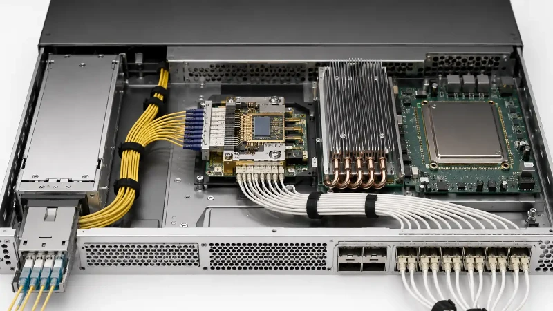
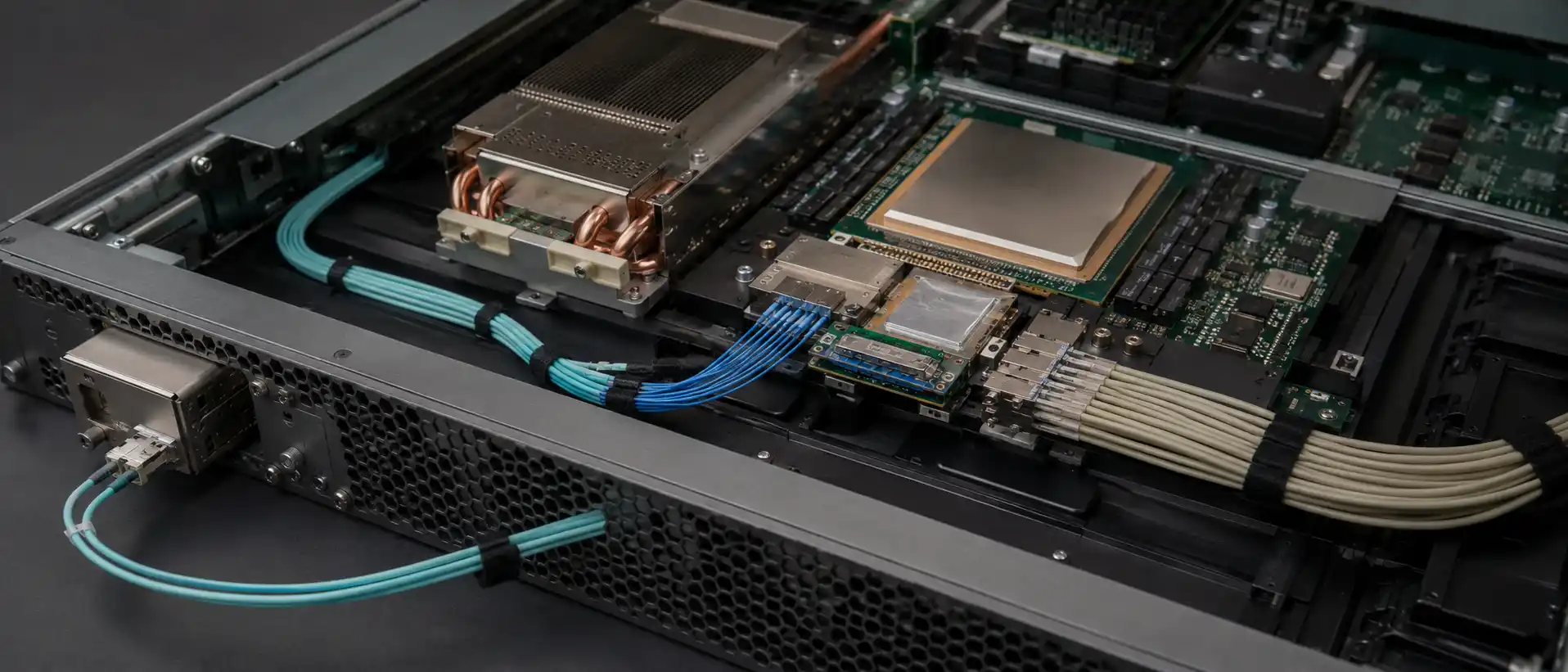
Corning's published CPO material describes exactly this arrangement: FAU assemblies containing mixed single-mode and polarization-maintaining fibers, with pluggable laser source modules at the faceplate connected to the PICs by PM fibers. The company also notes why these assemblies are difficult - high fiber counts, mixed SM/PM populations, micro-optic integration, and very tight alignment tolerances all in one component. Anyone specifying silicon photonics fiber cabling is dealing with two different fiber types with two different jobs in the same harness.
One frequently repeated claim is worth correcting. Corning's CPO FlexConnect fiber, launched at OFC 2025, is described by Corning as single-mode and bend-resilient, optimised for short inside-the-box CPO runs. It is not described as a PM fiber, and it is not described as a product developed specifically for one customer. Corning does have a CPO ecosystem relationship with NVIDIA, and Corning does supply PANDA PM fiber - but those are three separate facts and combining them into one produces a claim none of them supports.
Is PM Fiber Required in Every CPO Architecture?
No. The OIF co-packaging work distinguishes between optical engines with integrated lasers and designs that rely on an external light source. Where the laser is bonded or flip-chipped onto the photonic die, there is no external laser feed and therefore no PM harness - the polarization is fixed by the on-chip geometry. PM fiber becomes necessary specifically when light has to travel some distance, through connectors, before reaching a polarization-sensitive coupler.
Both approaches are in development across the industry. Treating PM fiber as an absolute requirement of CPO overstates the case; treating it as a requirement of external-laser CPO is accurate.
Specifications That Decide Whether a PM Fiber Suits CPO
"PM fiber" is not a single product. A gyroscope-grade fiber and a CPO-grade fiber may both use a PANDA structure and still be unsuitable substitutes for each other. The parameters that separate them:
- Operating wavelength - PM fiber is optimised per band (850, 980, 1310, 1550 nm and others); using it far from its design wavelength degrades both attenuation and polarization performance.
- Polarization extinction ratio (PER) - the ratio of power in the intended axis to power in the orthogonal one, in dB. This is an assembly-level number: fiber, splices, connectors and mounting all contribute.
- h-parameter - polarization crosstalk per unit length, the fiber's intrinsic figure of merit, independent of assembly quality.
- Beat length - shorter is better for resisting perturbation.
- Axis alignment tolerance - the dominant error in practice. Power coupled into the wrong axis scales as sin2θ, so PER from misalignment alone is roughly −20 log10(tan θ): about 35 dB at 1°, about 26 dB at 3°, about 21 dB at 5°. That relationship is why connector key orientation and splicer axis recognition are not optional.
- Cladding and coating diameter - inside-the-box CPO harnesses often use reduced-coating fiber to hit the required density.
- Minimum bend radius - routing inside a switch chassis is tight, and bend-induced stress affects PER as well as loss.
- Temperature stability - stress-based birefringence is temperature-dependent, and a switch package is a hot, thermally cycling environment.
- Array pitch and FAU coupling tolerance - for fiber array assemblies rather than discrete fibers.
The practical takeaway for anyone comparing quotations across an optical fiber portfolio: ask which of these are specified and at what confidence, and whether the number refers to bare fiber, a pigtail, a ribbon, or a fully connectorised assembly. Those four things have very different prices and very different performance.
PM Fiber Before CPO
The narrative in which PM fiber was a military-only material until AI discovered it is too tidy. Fiber optic gyroscopes are a long-standing and important application - they depend on polarization stability to resolve rotation via the Sagnac effect - but manufacturer catalogues have listed telecom, laser and sensing applications for decades. PM fiber has been used in fiber lasers and amplifier pigtails, in polarization-sensitive modulators, in coherent transceiver components such as tunable lasers and integrated coherent receivers, in fiber optic current and hydrophone sensors, and in quantum and laboratory optics.
What CPO changed is volume and product form, not physics. Demand shifted from short discrete pigtails toward high-count, precisely oriented harnesses and arrays produced at data-centre scale, which is a manufacturing challenge rather than a materials discovery.
What Is Confirmed and What Is Not
Confirmed from primary sources:
- OIF has published an ELSFP Implementation Agreement defining a front-panel pluggable external laser source form factor for co-packaged optical systems, alongside a 3.2 Tb/s co-packaged module IA and a co-packaging framework document.
- NVIDIA has announced Quantum-X InfiniBand Photonics and Spectrum-X Ethernet Photonics CPO switches, with commercial availability stated for 2026, citing roughly 3.5x power efficiency and 10x resiliency improvements.
- Corning has publicly described CPO FAU assemblies containing mixed SM and PM fiber, with faceplate laser modules connected to PICs by PM fiber.
Not verifiable from public primary sources, and therefore not asserted here: the frequently circulated figures for the share of global PM fiber consumption going to defence gyroscopes, per-metre prices for gyroscope-grade versus CPO-grade PM fiber, and claims that specific PM FAU suppliers have sold out capacity for the following year. These appear in supply-chain commentary without named reports, dates, regions, or a stated basis - bare fiber length, revenue, or assembled components. A CPO-grade PM assembly does command a large premium over commodity single-mode fiber, but the premium reflects axis-oriented assembly, connectorisation and yield, not the glass alone, and a single per-metre figure is not a meaningful way to express it.
If you need those numbers for a business case, get them from a named market report or a supplier quotation with the specification, quantity and product form attached. Anything else is a rumour with a decimal point.
Frequently Asked Questions
Q: Does PM Fiber Maintain Any Polarization State?
A: No. It maintains a linear polarization launched along its slow or fast axis. Circular or arbitrarily oriented input light is not preserved, and misaligned linear light degrades progressively with the misalignment angle.
Q: What Happens If The Launch Axis Is Misaligned?
A: Power splits between the two eigenmodes. The extinction ratio falls according to roughly −20 log10(tan θ), and the output polarization becomes sensitive to temperature and bending again, because the two components beat with a phase difference that varies with the environment.
Q: Can Standard Single-Mode Fiber Replace PM Fiber In A CPO Laser Feed?
A: Not without adding compensation. SMF can carry the light, but the state arriving at a polarization-sensitive grating coupler would drift with routing and temperature, producing a time-varying insertion loss. The alternatives - active polarization controllers or polarization-diverse couplers - add cost, power and die area.
Q: Is PM Fiber The Same As The Fiber Used In Fiber Optic Gyroscopes?
A: Both commonly use a PANDA structure, but the specifications differ. Wavelength, coating and cladding geometry, stress-region design, beat length, PER, bend performance, temperature range and assembly form all vary by application. Assuming interchangeability from structure alone is a specification error.
Q: Do All CPO Switches Need PM Fiber?
A: Only those with external light sources. Architectures with lasers integrated onto the photonic die do not require a PM harness.
Q: Why Are PM FAUs Harder To Manufacture Than Standard FAUs?
A: A standard FAU aligns fiber cores in x, y and z. A PM FAU adds a fourth degree of freedom - rotational alignment of each fiber's stress axis - across arrays that may contain dozens of fibers, often mixed with single-mode fibers in the same assembly, and the tolerance must survive curing, handling and thermal cycling.
Summary
- PM fiber preserves a linear polarization aligned to one eigenaxis; it does not stabilise arbitrary states.
- It works by making birefringence large and controlled, suppressing rather than eliminating coupling between the two polarization modes.
- PANDA is the most common design, not the only one.
- External-laser CPO uses PM fiber because silicon photonic grating couplers and modulators are polarization-sensitive, not because the systems are coherent - current NVIDIA engines use direct-detect PAM4.
- PM fiber carries CW light inbound; modulated data leaves on standard single-mode fiber. Both live in the same FAU harness.
- PER, beat length, axis alignment tolerance, wavelength and temperature stability decide whether a given PM fiber is fit for CPO. Structure alone does not.
- Circulating price and market-share figures for PM fiber lack traceable sources and should not be used in a business case without one.