




Submarine cable repair takes more than locating a break. Fault measurements must be matched to the installed route, a suitable vessel must reach the site, and compatible cable and joints must restore the damaged section. Applicable optical and electrical tests then confirm the repair. Network traffic may recover sooner through an alternative route, but that does not mean the damaged cable is back in service.
The distinction matters when assessing an outage or specifying a new cable link. Faster diagnosis can improve the response, while cable construction, route records, spare compatibility and marine access determine whether that information can be turned into a completed repair.
Fault Location, Cable Repair and Traffic Recovery Are Different Outcomes
A fault-location result answers where damage is likely to be. Physical repair restores the cable and its required functions. Traffic recovery restores connectivity for users. These outcomes depend on different resources and need separate completion criteria.
| Outcome | What establishes it | What it does not establish |
|---|---|---|
| Fault localized | Test evidence identifies an affected section or distance | The cable has been recovered or repaired |
| Cable repaired | The replacement section and joints pass the required acceptance tests | Every affected service has returned to its normal route |
| Traffic restored | Available network paths carry the affected traffic | The failed cable is physically intact or full redundancy has returned |
APNIC's analysis of submarine cable resilience explains how network operators can reroute traffic across other cable systems. Such recovery depends on usable alternative capacity. A route that exists on a map is not necessarily available to carry the displaced traffic at the required service level.
The Cable Architecture Determines How a Fault Can Be Located
An unrepeatered link and an amplified transoceanic system do not present the same test path. Their repeatered and repeaterless cable systems differ in submerged equipment, optical supervision and, where applicable, electrical power feeding. The test method must fit that architecture.
Optical and Electrical Evidence Answer Different Questions
Optical reflectometry measures returned light to identify changes along a test path. A conventional OTDR measurement suitable for an accessible cable span should not be assumed to characterize an entire amplified submarine system. ITU's submarine system design guidance distinguishes end-section OTDR measurements from coherent OTDR methods used for long-distance repeatered-system fault location.
Where a system has a metallic power conductor, electrical measurements can help investigate conductor and insulation faults. An electrical fault does not automatically mean every optical fiber is broken, and an optical event alone does not establish the condition of the power-feed path. Supervisory information and applicable electrical tests complement the optical evidence.
Faster Acquisition Improves Diagnosis Within Its Own Scope
Fault-localization speed includes connecting and configuring the test, acquiring the measurement, interpreting it and matching the result to the installed system. A short acquisition still needs to produce usable evidence of which fiber pairs and cable sections are affected.
EXFO describes co-propagation optical time-domain reflectometry (C-OTDR) for amplified submarine paths. Its term differs from coherent OTDR in the ITU guidance. In either case, operators need a method supported by their system architecture, baseline records and acceptance plan. An acquisition-time figure should state the instrument, topology and test conditions.
A Distance Reading Must Be Matched to the Installed Route
Reflectometry provides distance along an optical path, not a ready-made seabed coordinate. Cable slack, fiber length within the cable, the configured propagation parameters and previous repairs can affect the relationship between measured distance and geographic position.
The installation record connects these two descriptions of the system. Route position lists, cable lengths, joint locations, landing offsets and earlier repair records help translate a fault indication into a search area. The ICPC recommendations catalogue explicitly identifies accurate load-and-lay reporting and route position information as important to maintenance.
Baseline traces add context. A new event can be compared with the accepted installation record rather than interpreted without a reference. Distributed acoustic sensing for submarine cable monitoring may add evidence of activity near the route, but an acoustic event is not, by itself, confirmation of cable damage.
A Repair Must Restore the Cable Assembly
Repairing a submarine telecommunications cable involves more than joining optical fibers. The replacement section and joint arrangement must fit the cable's optical, mechanical and environmental requirements, as well as electrical requirements where power feeding is present.

Replacement Cable Must Fit the Installed System
Matching fiber count alone is insufficient. The repair design also considers fiber compatibility and splice behavior, cable dimensions, strength-member and armor arrangements, sealing and the handling requirements of recovery and deployment. For powered systems, conductor continuity and insulation are additional interfaces.
Compatibility is especially important where cable construction changes along a route. A shore approach, an armored shallow-water section and a lightweight deep-water section can impose different requirements on the spare cable and joint design. A replacement that has acceptable optical loss still needs to form a mechanically and environmentally suitable assembly.
Recovery and Redeployment Can Change the Optical Budget
The damaged section is recovered or otherwise accessed under a repair plan, replaced and returned to the seabed. The operation can introduce additional cable length and joints. Their attenuation needs to be considered alongside existing system margin.
ITU-T G.971's repair guidance distinguishes shallow- and deep-water repair conditions and recognizes that deep-water work can require extra cable and, in some circumstances, an additional repeater. That is a system engineering consideration, not a requirement to add a repeater after every repair.
Recovery loads, sea conditions and the final seabed placement also affect the operation. Electrical isolation and power safety are managed through the operator's and marine contractor's approved procedures; a fiber-splicing procedure alone does not address those hazards.
Repair Time Depends on the Stage Being Measured
A repair estimate needs a defined starting point and endpoint. Fault notification to vessel departure, transit to the site, marine repair work and final acceptance are different intervals. Some preparation activities can run in parallel, so they should not automatically be added into a single forecast.
At its 2026 plenary, ICPC reported 2025 repair data including 178 repairs, an average notification-to-departure interval of 23.4 days and an average transit interval of 7.7 days. These are reported dataset averages for particular stages. They do not predict an individual project's total outage duration.
Vessel availability, permissions, transit distance, weather, seabed access and the availability of suitable spares can each become the limiting condition. Reducing test acquisition time will not remove a weather restriction, but earlier, reliable fault information can allow other preparations to begin sooner.
The ITU-ICPC resilience report approved in July 2026 addresses timely deployment and repair alongside risk reduction and geographical diversity. These are recommendations for coordinated action, not a universal repair-time guarantee.
Acceptance Testing Confirms More Than a Successful Splice
A satisfactory splice-loss result is one part of repair acceptance. The relevant fiber paths, repaired section and complete system need the tests appropriate to their design and the agreed acceptance criteria. Powered systems also require the applicable electrical integrity checks.
The operator needs evidence that the repaired assembly can return to its intended operating condition, with any changes in loss or system margin understood. Updated traces and repair records then become the reference for the next incident. Confirmation should be coordinated before the repair vessel is released from the task.
ITU-T G.976 addresses testing of submarine optical cable systems. The current catalogue lists the November 2025 edition; its published summary notes additions concerning DC resistance and electrical integrity testing. A test plan should identify the applicable edition and system-specific procedures rather than treating an older generic test list as complete.
Cable Selection Shapes Future Repairability
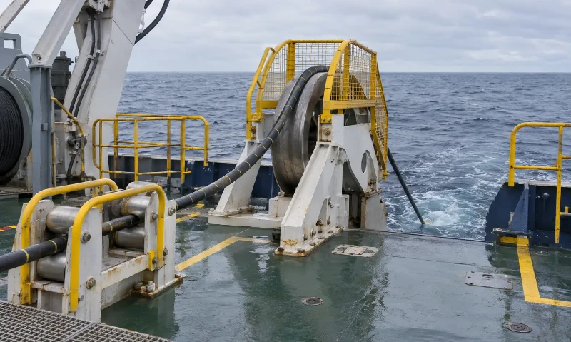
For a new link, maintainability begins with the proposed cable construction and its interfaces. A heavier armor design can address certain mechanical risks, but weight and stiffness also affect handling. A repair stock plan must therefore consider the cable designs and joint interfaces actually installed along the route.
The same principle applies to route diversity. Two systems may share a landing approach or other vulnerable corridor; buying capacity on both does not necessarily remove a common physical exposure. Diversity should be assessed against the failure scenario and the alternative capacity available during repair.
Hengtong supplies underwater fiber optic cable for route-specific construction requirements. A shorter water crossing and an amplified ocean system need to be assessed against their own depth, route, loading and interface conditions.
For cable supply engineering, specify the route depth and seabed conditions alongside recovery loads, armor transitions and the required joint interfaces. These inputs connect the cable construction to the way a damaged section could later be replaced.