




Selecting a fiber optic cable for a six-axis robot requires more than choosing a bend-insensitive fiber. The complete cable assembly must accommodate the robot's actual movement, including repeated bending, wrist rotation, torsional loading and changing cable routes, without exceeding the permitted optical loss.
G.657.A2 fiber can help reduce macrobending loss, but its fiber-level bending characteristics do not establish the torsion resistance or service life of a finished robotic cable. Cable construction, internal component arrangement, jacket materials, strain relief and connector termination must also be evaluated.
For industrial automation engineers and equipment buyers, the key is to match the complete fiber optic cable assembly to the robot's motion profile and verify its optical and mechanical performance under representative operating conditions.
How Six-Axis Robot Motion Loads a Fiber Optic Cable
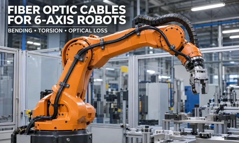
A six-axis industrial robot uses multiple rotating joints to position its end effector throughout a three-dimensional working area. A fiber optic cable routed along the robot arm must accommodate changes in joint position without becoming excessively stretched, twisted or compressed.
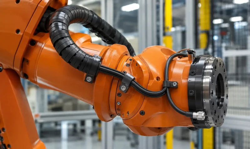
The wrist section deserves particular attention. Movement around the fifth and sixth axes can change the cable's orientation and routing geometry. Depending on the cable attachment points and available free length, this movement may introduce repeated bending, torsion or both.
Dynamic Bending and Axial Torsion Are Different Loads
Bending changes the curvature of the cable. Torsion rotates the cable around its longitudinal axis. Although both can occur during the same robot movement, they place different mechanical demands on the cable construction.
| Mechanical load | How it occurs | Potential effect |
|---|---|---|
| Dynamic bending | The cable repeatedly changes direction as robot joints move. | Changes in fiber curvature and possible bending-related attenuation. |
| Axial torsion | The cable rotates around its longitudinal axis when joint movement is transferred through restrained cable sections. | Mechanical stress within the cable structure and at restrained sections. |
| Combined bending and torsion | The cable bends while its orientation changes during wrist movement. | More complex mechanical loading affecting the cable, protective jacket and terminations. |
| Repeated contact and abrasion | The cable moves against robot structures, guides or nearby equipment. | Outer jacket wear and possible exposure of internal components. |
A robot's joint rotation does not automatically equal the torsion angle experienced by its cable. The actual deformation depends on the cable route, restraint positions, free length and whether a dedicated cable guide allows the cable to rotate or redistribute movement.
Cable Routing Determines Where Mechanical Stress Occurs
The installation arrangement has a direct influence on cable movement. A cable routed through an external dress pack may experience different mechanical loading from one installed inside a dedicated protective guide.
Several details need to be evaluated before selecting a robotic fiber optic cable:
- Fixed attachment points: Restraints determine where joint movement is transferred into the cable. Poor positioning can concentrate torsional or bending stress in a short section.
- Free cable length: Insufficient length can restrict movement and increase tension, while excessive slack may create interference with surrounding equipment.
- Guide geometry: Cable carriers and protective guides influence the available bend radius and the path followed during joint movement.
- Moving contact points: Repeated rubbing against metal structures or other cables can damage the outer jacket.
- Connector positioning: Terminations should be located and supported to prevent unnecessary mechanical loading at the connection interface.
A suitable cable arrangement must accommodate the complete working envelope of the robot, not just the cable's position when the arm is stationary.
How Bending and Torsion Affect Optical Transmission
Mechanical movement can affect optical transmission through changes in fiber curvature, localized pressure and physical damage. Understanding the difference between macrobending, microbending and torsional loading helps identify the appropriate fiber and cable-level tests.
Macrobending Loss
Macrobending loss occurs when an optical fiber is bent around a relatively large-scale curve. As the bend becomes tighter, part of the guided optical power can escape from the core, increasing attenuation.
The amount of loss depends on the fiber design, bend radius, operating wavelength and number of turns. Bend-insensitive single-mode fibers are designed to reduce this effect under specified test conditions.
However, a fiber's macrobending performance does not establish the minimum dynamic bend radius of the finished cable. Buffering, cable structure and internal mechanical constraints can change the actual curvature experienced by the fiber.
Microbending Loss
Microbending results from small, localized distortions along the optical fiber. Uneven pressure, cable compression and mechanical contact can create these distortions and increase optical attenuation.
During repeated robot movement, internal cable components may shift or experience changing pressure. Even when the overall cable bend radius remains within its specified limit, localized deformation may affect the fiber.
This is why both the optical fiber and its surrounding cable construction need to be considered during mechanical qualification.
Temporary Attenuation Changes and Permanent Damage
Optical performance should be evaluated both while the cable is moving and after mechanical loading has stopped.
| Observed condition | What it indicates | Evaluation method |
|---|---|---|
| Temporary optical loss variation | Transmission changes during movement and may recover when the cable returns to its original position. | Continuous optical power monitoring during cycling. |
| Residual attenuation increase | Additional optical loss remains after the mechanical load is removed. | Comparison of pre-test and post-test optical measurements. |
| Localized optical event | A new loss or reflection event may indicate a damaged section, splice or connection. | OTDR measurement before and after mechanical testing. |
| Physical cable degradation | Jacket wear, deformation or damage around restraints and terminations. | Visual and mechanical inspection of the complete assembly. |
A cable that passes an optical test before and after movement may still experience temporary attenuation changes during operation. Where uninterrupted optical transmission is required, dynamic optical monitoring is necessary.
What G.657.A2 Fiber Can and Cannot Provide
ITU-T G.657 defines characteristics for bending-loss-insensitive single-mode optical fiber and cable. G.657.A2 is designed to provide improved macrobending performance compared with conventional G.652.D fiber.
For applications involving constrained optical routing, G.657.A2 bend-insensitive single-mode fiber can be evaluated as one component of the cable design.
G.657.A2 Bending Performance
ITU-T G.657 (08/2024) identifies a minimum design radius of 7.5 mm for G.657.A2 fiber. This is a fiber-category design value, not a universal dynamic bend-radius limit for a completed robotic cable assembly.
Product-specific data may state smaller bending values for particular fiber variants. Before applying such a value to a cable design, confirm the fiber specification, test geometry, operating wavelength, number of turns and applicable attenuation limit.
Official reference: ITU-T G.657 (08/2024), Characteristics of a bending-loss insensitive single-mode optical fibre and cable.
Why G.657.A2 Does Not Establish Torsion Resistance
G.657.A2 addresses optical fiber bending-loss characteristics. It does not specify the torsional fatigue life of a finished cable, the allowable rotation of a robot wrist or the number of movement cycles an assembled cable can withstand.
A fiber may maintain acceptable optical performance under a specified bending test while the complete cable experiences excessive mechanical stress during repeated rotation.
Consequently, G.657.A2 should be evaluated alongside the cable's internal structure, mechanical protection and application-specific movement requirements. Fiber selection alone is not sufficient to qualify a robotic fiber optic cable.
How Cable Construction Affects Robotic Applications
The finished cable must protect the optical fiber while accommodating the mechanical movement imposed by the robot. Its performance depends on the interaction between internal components, reinforcing materials, outer jacket and termination design.
Fiber Buffering and Internal Cable Arrangement
Buffering protects the optical fiber against external contact and helps control how mechanical loads are transferred to the glass.
The internal arrangement of fibers and reinforcing components also affects how bending and rotation are distributed through the cable. A construction intended primarily for stationary installation should not automatically be considered suitable for continuous torsional movement.
For dynamic applications, the complete construction needs to be evaluated for fiber protection, relative component movement and mechanical fatigue.
Strength Members and Mechanical Protection
Strength members help manage tensile loading and protect the cable against mechanical forces. Their material, location and interaction with other cable components influence the overall mechanical behavior.
A cable designed to withstand installation pulling tension is not necessarily qualified for repeated torsional movement. Tensile strength, bending performance and torsional fatigue are separate evaluation requirements.
Outer Jacket and Environmental Resistance
The outer jacket protects the cable from abrasion, moisture, chemicals and other environmental exposure. Material selection should reflect the robot's operating environment and the contact conditions along the cable route.
Where the cable passes through moving guides or exposed robot-arm sections, jacket wear resistance and flexibility need to be considered together. A jacket that protects against abrasion but creates excessive stiffness may not suit every dynamic routing arrangement.
Connector Termination and Strain Relief
Connector terminations are particularly important because repeated movement can transfer mechanical loads to the cable entry point.
Strain relief should prevent excessive pulling and bending forces from reaching the fiber termination. Connector type, cable entry geometry, boot design and available clearance should also match the equipment interface.
These requirements are relevant when evaluating fiber optic cable assemblies for industrial and manufacturing applications, where robotic controls, flex life, strain relief and connector compatibility all influence connection reliability.
How to Specify a Fiber Optic Cable for a 6-Axis Robot
A useful RFQ specification should describe the robot's actual movement and the mechanical conditions imposed on the cable. Terms such as flexible, high-flex or torsion-resistant are not sufficient without defined test conditions.
| Specification item | Information to define | Why it matters |
|---|---|---|
| Robot movement | Relevant axes, joint rotation, movement sequence and operating duty cycle. | Establishes the actual cable motion profile. |
| Torsion | Angular displacement, active cable length, rotation direction and movement speed. | Defines the rotational loading applied to the cable. |
| Dynamic bend radius | Minimum radius during movement and the measurement reference used. | Establishes the bending conditions for mechanical evaluation. |
| Cable routing | Fixed points, free length, guide arrangement and connector positions. | Determines how robot movement is transferred to the cable. |
| Mechanical cycling | Cycle count, movement frequency, acceleration and test duration. | Provides a defined basis for evaluating repeated mechanical exposure. |
| Operating environment | Temperature, oil, coolant, cleaning agents, moisture and abrasion exposure. | Determines material and jacket requirements. |
| Optical requirements | Fiber type, fiber count, operating wavelength, transmission requirements and allowable attenuation. | Ensures the cable meets the communication system requirements. |
| Connection requirements | Connector type, interface compatibility, termination arrangement and strain relief. | Prevents connection-related mechanical and optical problems. |
For a custom cable design, these requirements should be evaluated together rather than specified independently. The internal cable construction, reinforcement, jacket and termination must match the same movement profile used for qualification.
How to Test a Robotic Fiber Optic Cable
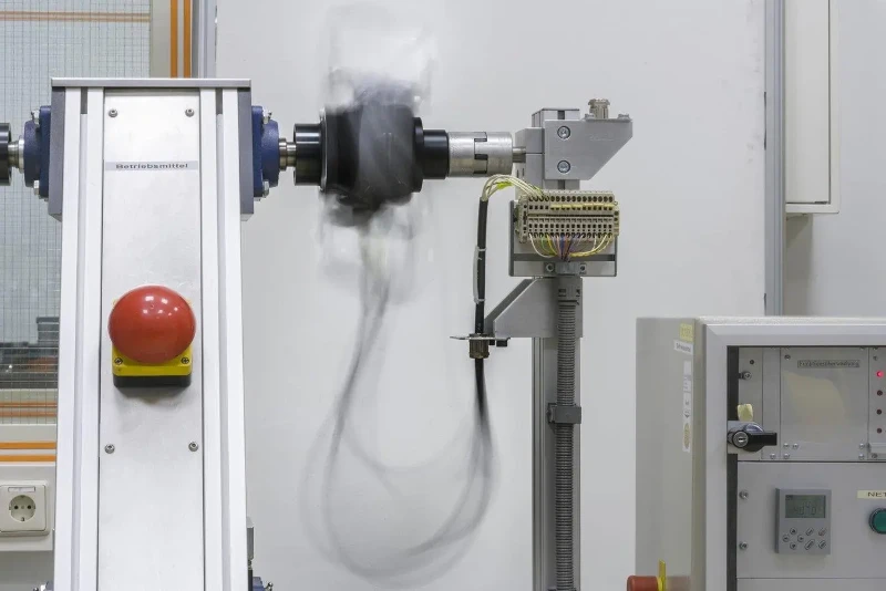
Mechanical and optical testing should reproduce the cable's intended installation and movement conditions. Testing an isolated optical fiber or a straight cable sample does not establish the performance of the complete robotic assembly.
Reproduce the Actual Cable Routing
The test setup should represent the cable's installed configuration, including its effective free length, fixed points, guides and connector terminations.
The minimum dynamic bend radius and torsional movement should be defined from the robot's operating sequence. Where bending and torsion occur simultaneously, the qualification test should reproduce their combined effect.
Evaluate Bending and Torsion Separately and Together
Separate tests help identify how the cable responds to individual mechanical loads. Combined testing then evaluates the interaction between bending and torsion under representative operating conditions.
Important test records include:
- Applied torsion angle and effective specimen length.
- Minimum dynamic bend radius.
- Movement speed and frequency.
- Cycle count and test duration.
- Operating and test temperature.
- Cable routing, restraint and termination arrangement.
Test conditions and acceptance limits must be agreed before testing. A cycle count without the associated movement profile and inspection criteria cannot establish a meaningful service-life expectation.
Monitor Optical Transmission During Movement
Use a stable optical source and an optical power measurement system to monitor transmission while the cable is moving. The measurement system must have sufficient response time to capture attenuation changes at the frequency of the robot's movement.
Record three measurement stages:
- Before testing: Establish the initial optical power and attenuation baseline.
- During testing: Record optical transmission throughout the movement sequence to identify temporary variations and interruptions.
- After testing: Repeat optical measurements and compare the results with the original baseline to identify residual degradation.
OTDR testing before and after mechanical cycling can help locate persistent optical events. It should not replace continuous optical power monitoring when temporary transmission changes during movement are important.
Inspect the Complete Assembly After Cycling
Optical measurements should be accompanied by a physical inspection. Check the outer jacket, cable entry points, restraints, protective guides and connector terminations for wear or deformation.
Any acceptance decision should consider both optical performance and mechanical condition. Stable transmission does not by itself establish that the cable has retained its structural integrity.
What IEC 60794-1-107:2025 E7 Torsion Testing Establishes
IEC 60794-1-107:2025 defines the E7 torsion test method for optical fiber cables. It establishes test procedures for assessing torsional performance under defined conditions.
The standard's published scope covers optical fiber cables used with telecommunications equipment and devices employing similar techniques, as well as cables combining optical fibers and electrical conductors.
It provides a standardized basis for torsion testing, but it is not a specific six-axis robot cable qualification standard.
Why E7 Testing Is Only One Part of Robot Cable Qualification
A torsion test evaluates the cable under the conditions defined by the applicable test method. Actual robot operation may also involve changing bend radii, repeated directional movement, cable contact and combined mechanical loading.
Passing a torsion test alone therefore does not establish:
- Performance under every six-axis robot movement sequence.
- Optical stability during combined bending and torsion.
- Compatibility with a particular cable dress pack or routing arrangement.
- Long-term service life under an unspecified operating cycle.
IEC E7 results should be considered alongside application-level mechanical testing, dynamic optical monitoring and post-test inspection.
Official reference: IEC 60794-1-107:2025, Torsion, method E7.