





The explosive growth of cloud computing, artificial intelligence, and big data analytics has driven demand for high-bandwidth, low-latency, energy-efficient, and cost-effective optical transceivers. In the context of network architecture evolving from 100G to 400G and beyond, the QSFP-DD packaging form factor has become the industry's answer to these challenges, doubling the available I/O density while maintaining backward compatibility with existing QSFP infrastructure. Among the various QSFP-DD variants, the DR4 (Dual Density 4-lane) solution stands out particularly in short-distance applications.
Importance of QSFP-DD DR4
QSFP-DD DR4 optical transceivers are a key technology for data center operators to upgrade their networks to 400G speeds without completely overhauling existing infrastructure. These modules deliver 400Gbps throughput over single-mode fiber up to 500 meters, serving intra-data center interconnections, top-of-rack to core switch connections, and high-performance computing clusters. The DR4 solution primarily addresses maximizing port density in space-constrained environments while providing a clear migration path from legacy systems.
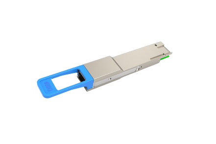
QSFP-DD DR4 Optical Module
Data rate architecture: Each DR4 module delivers 400G throughput by utilizing four parallel optical channels, with each channel operating at 100Gbps. This 4x100G architecture employs PAM4 encoding to achieve high data rates while maintaining signal integrity.
Transmission distance: DR4 modules support transmission over single-mode fiber (OS2) up to 500 meters. This distance is optimized for intra-data center applications where extremely long distances are not required, but reliable high-speed connectivity is essential.
Power consumption: Typical power consumption is below 12 watts. Advanced thermal management ensures reliable operation even in high-density deployments.
Physical interface: The module features an 8-lane electrical interface compliant with the QSFP-DD specification, housed in a form factor of approximately 18.35mm × 89.4mm. The dual-density design allows 36 ports in a 1U switch, doubling the port density compared to traditional QSFP modules.
Fiber type and connector: DR4 typically uses parallel single-mode fiber (OS2) with MPO connectors, delivering 400Gbps transmission within 500 meters. This is distinct from QSFP-100G-DR-S style single-channel approaches, as the DR4 module operates as a complete 400G transceiver solution.
Temperature range: Most DR4 modules operate reliably within the range of 0°C to 70°C.
Core Technologies and Principles
PAM4 Modulation Technology
PAM4 (4-Level Pulse Amplitude Modulation) represents a fundamental shift in optical signal technology. Unlike traditional NRZ (Non-Return-to-Zero) encoding, which uses two signal levels to represent binary data, PAM4 employs four distinct amplitude levels to encode two bits per symbol.
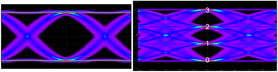
How PAM4 works: In a PAM4 signal, each symbol can represent one of four states: 00, 01, 10, or 11. This effectively doubles the data transmission rate without increasing the baud rate. For example, a 26.5625 GBaud signal using PAM4 can transmit 53.125 Gbps of data, whereas using NRZ it would only transmit 26.5625 Gbps.
Advantages for DR4: PAM4 modulation enables DR4 modules to achieve 100Gbps per channel without requiring excessively high-frequency electronic components or extremely tight dispersion tolerances.
Signal considerations: Compared to NRZ, PAM4 signals have lower noise margin due to the smaller spacing between amplitude levels. Advanced forward error correction (FEC), digital signal processing (DSP), and precision analog circuitry work together to maintain acceptable bit error rates even under reduced signal-to-noise conditions.
Gearbox Technology
Gearbox is a critical component that bridges the speed mismatch between the host electrical interface and optical channel rates. In QSFP-DD DR4 modules, the Gearbox performs complex data rate conversion and channel allocation. The host provides eight 50Gbps electrical channels (8×50G PAM4) at the module interface. The Gearbox converts this 8-channel 400G electrical signal into four 100Gbps optical channels (4×100G PAM4) for transmission over fiber. The protocol-aware functionality of modern Gearbox maintains packet boundaries, manages flow control, and correctly aligns data across multiple channels to prevent data corruption during conversion.
Performance optimization: The Gearbox design incorporates buffering, clock domain crossing circuits, and adaptive equalization to minimize latency and jitter. These features minimize the overhead that electrical-to-optical conversion adds to the overall transmission path.
MDC Interface
The MDC interface is a standardized I2C-compatible protocol that provides basic monitoring and control capabilities for QSFP-DD modules. Through the MDC interface, network operators can access real-time information regarding module temperature, supply voltage, transmit optical power, receive optical power, and laser bias current. The MDC interface allows the host to configure module parameters, supporting diverse deployment scenarios and optimization strategies.
QSFP-DD modules implement a standardized memory map defined by industry specifications, ensuring consistency of the management interface across vendors, simplifying network management, and reducing integration complexity. These three core technologies work in concert to achieve reliable 400G transmission. QSFP-DD DR4 optical modules must comply with the QSFP-DD MSA standard, IEEE 802.3bs standard, and OIF CEI-56G-PAM4 standard.
Comparison with FR4/LR4
The QSFP-DD 400G series includes multiple interface types, each optimized for different transmission requirements. The three mainstream solutions are DR4, FR4, and LR4.
Comparison of the three 400G interfaces:
|
Interface |
Nominal Wavelength (nm) |
Fiber Type |
Transmission Distance |
Optical Signal Rate |
Electrical Signal Rate |
Fiber Connector |
|
DR4 |
1310 |
Single-mode |
500m |
4×100G |
8×50G |
MPO-12 |
|
FR4 |
1271/1291/1311/1331 |
Single-mode |
2km |
4×100G |
8×50G |
Duplex LC |
|
LR4 |
1271/1291/1311/1331 |
Single-mode |
10km |
4×100G |
8×50G |
Duplex LC |
Optical Transmission Architecture:
|
Solution |
Architecture |
Fiber Usage |
Wavelength Multiplexing |
|
DR4 |
Parallel transmission |
8-core (4Tx + 4Rx) |
None, unified 1310nm |
|
FR4/LR4 |
CWDM wavelength division multiplexing |
2-core (1Tx + 1Rx) |
Yes, O-band 4 wavelengths |
Application Scenario Selection:
|
Scenario |
Recommended Solution |
Rationale |
|
In-facility TOR-Spine |
DR4 |
Distance <500m, most cost-effective |
|
Campus multi-building interconnection |
FR4 |
Distance 500m–2km |
|
Data center DCI |
LR4 |
Distance 2–10km |
|
Existing single-mode cabling |
DR4/FR4/LR4 |
Select based on distance requirement |
Note: The DR4 standard is defined for single-mode fiber applications. For multimode fiber use, please refer to other interface standards such as 400G SR8.
Regarding connector types, DR4 uses an MPO-12 parallel connector (8-core fiber ribbon), while FR4 and LR4 use duplex LC connectors (2-core single-mode). Deployments leveraging Cisco DAC cables should verify compatibility with the specific switch platform and module vendor prior to installation.
Advantages of DR4
On the physical layer, QSFP-DD DR4 optical modules can deploy 36 400G ports within 1U of rack space - double the port density of traditional QSFP - which translates directly into cost savings for data centers with tight rack space constraints. In terms of energy efficiency, DR4 modules keep power consumption below 12W, utilizing DFB or EML laser technology to achieve high-performance single-mode transmission; cumulative energy savings are significant at scale, while also reducing cooling system loads. Economically, DR4 uses single-mode fiber (OS2) to provide a reliable 500-meter transmission distance, with module costs 30–50% lower than FR4/LR4. Additionally, DR4 fully complies with QSFP-DD MSA and IEEE 802.3bs standards, ensuring multi-vendor interoperability. At the same time, QSFP-DD ports are backward compatible with QSFP/QSFP28 modules, supporting a phased network upgrade strategy that effectively protects existing investments.
FAQ
Q: Can a QSFP-DD DR4 module be plugged directly into a QSFP28 port?
A: No, it cannot be used directly. Although QSFP-DD ports are backward compatible with QSFP28 modules, the reverse is not true. The QSFP-DD module has a larger physical size and different interface pin definitions. To use a QSFP-DD module, the switch must be upgraded to one that supports QSFP-DD. This is an important consideration when planning upgrades from 100G platforms such as those using QSFP-100G-CR4 or QSFP-100G-LR4-S modules.
Q: What is the main disadvantage of PAM4 modulation compared to NRZ?
A: The main disadvantage of PAM4 is its higher signal-to-noise ratio requirement. Because it uses 4 levels instead of 2, the spacing between adjacent levels is smaller, making the signal more susceptible to noise and resulting in a relatively higher bit error rate. This is compensated through robust FEC (Forward Error Correction) and DSP technology.
Q: Does the DR4 module support hot-swapping? Will it affect other ports?
A: Yes, hot-swapping is supported - this is a basic requirement of the QSFP-DD standard. Modern switch designs ensure that inserting or removing a single module does not affect the operation of other ports.
Q: When upgrading from 100G, is it better to go directly to 400G or upgrade to 200G first?
A: If bandwidth demand is growing rapidly and rack space is constrained, upgrading directly to 400G QSFP-DD is more economical. If you are pursuing a phased upgrade and existing 100G equipment still holds value, QSFP56-DD or QSFP56 200G solutions may serve as a viable transitional option.