

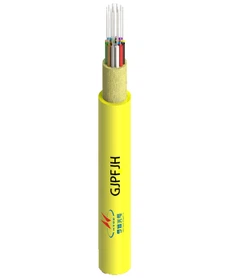



CPO (Co-Packaged Optics) integrates optical engines into the same package assembly as a host switch ASIC. NPO (Near-Packaged Optics) places optical engines close to the ASIC while keeping them as separately attached components. Both architectures shorten the high-speed electrical connection between the ASIC and the optical engine. The main difference is how closely the optical engine is integrated into the ASIC package and how the components are attached and serviced.
CPO and NPO do not shorten the optical fiber link between network devices. They change the electrical section inside the switch or computing system, before the signal is converted into light. That distinction is essential when comparing their power consumption, bandwidth density, packaging requirements and maintenance options.

Why the Electrical Signal Path Matters
In a conventional front-panel pluggable architecture, the switch ASIC sends high-speed electrical signals through SerDes lanes and PCB traces to an optical transceiver installed at the front panel. The transceiver converts the electrical data into optical signals, which then travel through fiber to another network device.
A simplified transmit path is:
Traditional pluggable optics: Switch ASIC → SerDes → PCB electrical channel → Front-panel optical transceiver → Optical fiber
As lane rates increase, the electrical channel between the ASIC and the transceiver becomes harder to design. Insertion loss, crosstalk, impedance discontinuities and package parasitics can reduce signal quality. The host may need stronger output drivers, more equalization or additional retiming and digital signal processing to maintain the required signal integrity.
CPO and NPO move the optical engine closer to the host ASIC. This reduces the length and electrical impairment of the high-speed channel, which can lower the amount of signal conditioning required. The exact benefit depends on the SerDes design, channel materials, optical engine interface and system architecture. In one example in its Co-Packaging Framework, the OIF describes a re-timed interface over approximately 50 mm of first-level packaging substrate. That is an example for a particular interface arrangement, not a universal CPO or NPO channel length.
The optical path is a separate part of the connection. Once the optical engine converts the signal, fiber carries it to the remote endpoint. The reach remains determined by the optical interface, fiber type, link budget and transceiver or optical-engine specification. Moving the optical engine closer to the ASIC does not turn a 100 m, 500 m or 2 km fiber link into a centimeter-scale link.
For comparison with the conventional architecture, Hengtong's high-speed transceiver module optical components category shows the type of optical components used in pluggable connectivity.

What Is Near-Packaged Optics (NPO)?
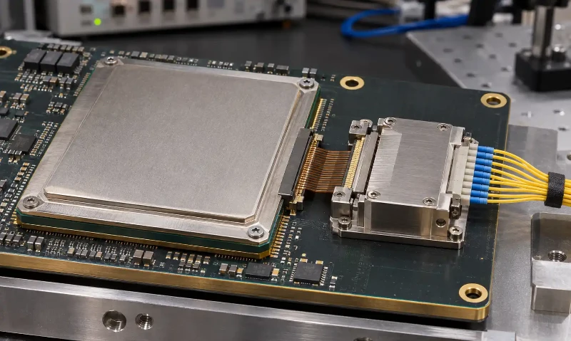
Near-Packaged Optics places an optical engine close to the host ASIC without treating the optical engine as a photonic component fabricated directly into the ASIC die. The engine remains a separate assembly connected through a short electrical interface. Depending on the platform, it may sit on a nearby substrate, use a socketed connection or be mounted in another near-package arrangement.
The term is not used with exactly the same mechanical definition by every supplier. The OIF's 2022 framework identifies one specific NPO arrangement in which a packaged ASIC and an optical engine are attached to a common substrate through sockets. The sockets allow the devices to be removed during assembly and rework. This is a useful reference architecture, but it should not be treated as a mandatory construction for every product marketed as NPO.
How NPO Places Optical Engines Near the Switch ASIC
In an NPO design, the ASIC and optical engine are physically close enough to reduce the high-speed electrical path compared with a front-panel pluggable module. The ASIC's SerDes connects to the electrical interface of the optical engine. Inside the engine, electronic and photonic components handle the conversion between electrical data and optical signals.
The shorter electrical channel can reduce signal loss and the need for extensive signal conditioning. The optical engine then connects to the system's fiber interface, which routes the optical signal toward the front panel or another optical connection point. Fiber routing, connector access and optical loss still need to be considered as part of the complete switch design.
NPO Socket Design and Optical Engine Serviceability
A socketed NPO implementation can make the optical engine or socket easier to remove during assembly, rework or service. A soldered implementation does not offer the same replacement process. Therefore, NPO should not automatically be described as field-replaceable; the attachment method and the system's service procedure determine what can actually be changed.
TE Connectivity's NPO socket design guidance identifies signal integrity, contact alignment, mechanical tolerance, compression force, PCB or substrate flatness, cold-plate integration and fiber management as related design considerations. A socket is not simply a plug-in feature. Its mechanical and electrical performance must be designed together with the optical engine and cooling structure.
NPO therefore offers a way to bring optics close to the ASIC while retaining more flexibility in component attachment than some fully integrated package designs. It still requires careful control of the electrical interface, mechanical stack-up and thermal environment.
What Is Co-Packaged Optics (CPO)?
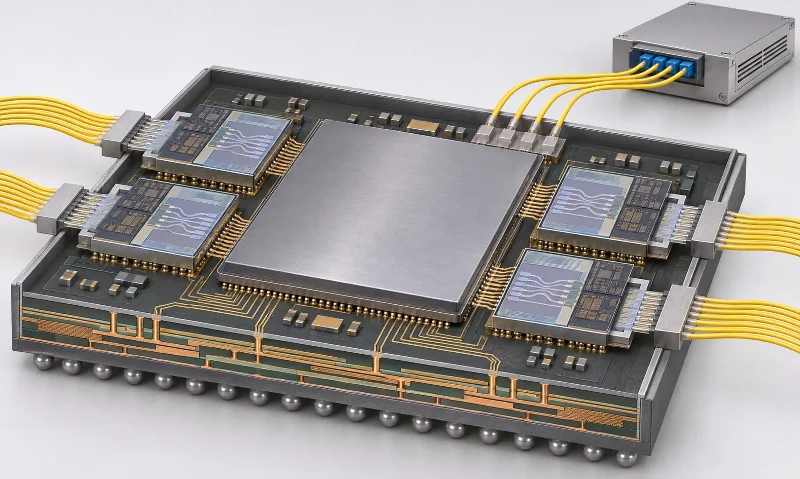
Co-Packaged Optics places the optical engine within the same package assembly as the host ASIC. The ASIC and optical engine may be separate dies or components, but they are integrated into a common package architecture rather than connected as a conventional front-panel transceiver.
This is a form of heterogeneous integration. It does not mean that the electronic logic and all photonic functions must be fabricated on one monolithic silicon die. A CPO assembly can combine an electronic ASIC, photonic components and supporting structures within a shared package design. The exact substrate, interposer and attachment method depend on the manufacturer's implementation.
The mechanical attachment method is a separate design decision from the architecture label. The OIF framework describes co-packaging assemblies with either socketed or soldered ASIC and optical-engine attachments. It also identifies a specific socketed arrangement of a packaged ASIC and optical engine on a common substrate as NPO. For this reason, "socketed" should not be treated as a synonym for every NPO design, and CPO should not automatically be assumed to mean permanently soldered in every implementation.
How CPO Integrates Optical Engines with Switch ASICs
A CPO optical engine is positioned close to the switch ASIC so that high-speed electrical signals travel through a short package-level connection. The optical engine commonly combines a photonic integrated circuit (PIC) with an electronic integrated circuit (EIC).
- PIC: Handles photonic functions such as optical waveguides, modulation and photodetection. Silicon photonics is one approach used to integrate these functions.
- EIC: Handles the electronic functions required to drive and receive high-speed signals, such as modulator drivers, transimpedance amplification and related control circuitry.
- Optical engine: Combines the required photonic and electronic functions to convert data between electrical and optical domains.
Keeping the electrical connection short can reduce channel loss and help support high-density optical I/O around a switch ASIC. The optical signal still leaves the package through a fiber attachment or optical connector. Package-level fiber attachment, alignment tolerance, optical loss and the physical routing of many fibers are therefore important parts of CPO system design.
For a related view of how silicon photonic devices affect the fiber layer, see Hengtong's article on 400G silicon photonics and fiber cabling.
CPO Thermal Management and External Laser Sources
Thermal design is a major part of CPO integration because the optical engine operates close to a high-power switch ASIC. Photonic components, electronic drivers and laser sources have different thermal requirements. The package, heat spreader, cold plate or other cooling structure must keep each component within its operating range without compromising signal integrity or optical alignment.
The laser source does not have to be located inside the optical engine in every CPO design. Some systems use an External Laser Source (ELS) to supply continuous-wave light to optical engines near the ASIC. Separating the laser from the hot switch package can improve the laser's thermal environment and allow the light source to be replaced independently.
The OIF's ELSFP 2.0 Implementation Agreement defines a pluggable form factor for external laser sources that deliver continuous-wave light to co-packaged optical engines. The laser module can be field-replaceable through a pluggable blind-mate connection. This does not mean that the CPO optical engine itself is also a front-panel replaceable module.
External lasers also introduce optical coupling and insertion-loss considerations. The OIF framework notes that separating the laser from the optical engine can improve thermal conditions, but the additional optical loss may require higher laser output power. Whether an internal or external laser is preferable depends on the optical budget, thermal design, reliability targets and service strategy.
CPO vs NPO: Key Technical Differences
The following comparison describes common architectural differences. It is not a universal specification for every vendor. Package design, socket selection, fiber attachment and service procedures can change the actual implementation.
| Technical feature | NPO | CPO |
|---|---|---|
| Optical engine location | Close to the host ASIC but retained as a separately attached component. | Integrated into the same package assembly as the host ASIC. |
| Electrical signal path | Short board-level or near-package connection between the ASIC and optical engine. | Very short package-level connection between the ASIC and optical engine. |
| Packaging approach | May use a socket, nearby substrate or another separate attachment arrangement. | Uses a common package architecture; the attachment method depends on the design. |
| Optical engine replacement | Can be easier when the engine uses an accessible socket or removable assembly. | Usually more dependent on package-level rework or system replacement; not determined by the CPO label alone. |
| Power consumption | Can reduce electrical-channel and signal-conditioning power compared with front-panel pluggables. | Can reduce the electrical interconnect power further through tighter integration, depending on the system. |
| Bandwidth density | Supports high-density optical connectivity while retaining a separate engine attachment. | Offers strong potential for high optical I/O density around the ASIC package. |
| Thermal design | Requires coordinated cooling for the ASIC, socket and nearby optical engine. | Requires close thermal co-design because the optical engine shares the ASIC package environment. |
| Main engineering trade-off | Short electrical paths with more flexibility in engine attachment and serviceability. | Higher package integration and density, with greater demands on packaging, fiber attachment and thermal design. |
Power Consumption and Bandwidth Density
Both architectures address the power and signal-integrity penalties associated with long high-speed electrical channels. The shorter the electrical path, the less channel loss and equalization may be required. CPO can push this approach further by placing the optical engine within the ASIC package assembly.
However, power savings are not determined by package placement alone. The host SerDes, retiming or DSP functions, optical engine design, laser source, cooling system and optical link budget all contribute to total power. A vendor's reported optical-interconnect saving should not be presented as the same percentage reduction in total switch or data-center power.
Bandwidth density also depends on the number of optical engines, lane rates, package edge space, fiber exits and cooling constraints. There is no fixed rule that assigns 1.6T to NPO and 3.2T or higher to CPO. The OIF's 3.2 Tb/s CPO Module Implementation Agreement defines a specific module for Ethernet switching applications and a 51.2 Tb/s aggregate switch use case. It does not establish a universal bandwidth threshold between NPO and CPO. See the OIF 3.2T Co-Packaged Module announcement.
Where OBO and LPO Fit
CPO and NPO are not the only ways to reduce the power or electrical reach of optical interconnects. On-Board Optics (OBO) and Linear Pluggable Optics (LPO) address different parts of the architecture.
| Architecture | Optical component placement | Main distinction |
|---|---|---|
| Traditional pluggable optics | Front-panel optical transceiver. | Provides a removable module and a familiar service model, but requires a longer electrical path from the ASIC. |
| LPO | Front-panel pluggable optical module. | The LPO MSA describes LPO as a pluggable module without an onboard DSP. It relies more heavily on host-side signal processing, changing the electrical architecture rather than the physical placement of the optical engine. |
| OBO | Optical engine mounted on the system PCB, separate from the ASIC package. | Moves optics onto the board and closer to the host chip without integrating them into the ASIC package. |
| NPO | Optical engine positioned near the ASIC, often using a nearby substrate or socketed arrangement. | Shortens the electrical path while retaining a separate engine attachment in relevant implementations. |
| CPO | Optical engine integrated into the ASIC package assembly. | Provides the closest package-level integration between the host ASIC and optical engine. |
The boundaries between OBO and NPO can vary in vendor terminology. Ericsson's technical review provides a useful architectural comparison of CPO, OBO, NPO and conventional pluggable optics. LPO should be considered separately because it describes the signal-processing design of a pluggable module rather than an optical-engine placement category.
These architectures can coexist in a network. A data center may use pluggable optics for some links, LPO where the host platform supports it, and NPO or CPO in selected high-density switching systems. The choice depends on the link budget, host ASIC, maintenance requirements and system-level design.
CPO and NPO in AI Data Center Networks
AI data centers generate high volumes of east-west traffic between GPUs, accelerators, memory resources and network switches. As switch bandwidth and port density increase, the electrical connection between the ASIC and optical interface becomes a more important part of the system power and signal-integrity budget.
In scale-out networks, optical links connect switches across racks, rows and data halls. In scale-up systems, high-bandwidth connections link tightly coupled accelerators and memory resources. The required reach, topology and service model differ between these applications, so CPO or NPO should be selected at the platform level rather than treated as a universal replacement for pluggable optics.
For disaggregated infrastructure, the optical fabric must connect compute, memory, storage and networking resources while meeting bandwidth, latency and reach requirements. Hengtong's overview of optical interconnect for data center disaggregation explains the wider network architecture in which these optical links operate.
The physical cabling layer remains important after the optical engine has converted the signal. High-density switches still need fiber routing, connector access, polarity control and a link-loss budget that matches the optical interface. For 800G AI networks, the 800G MPO guide for 16-fiber AI data center links provides a practical reference for fiber count and connector planning.
Copper and fiber also retain different roles in AI infrastructure. Short-reach electrical connections can remain practical where distance and power requirements allow, while optical links are used where reach, bandwidth density or signal integrity makes them more suitable. The application boundary is discussed further in Copper vs Fiber for AI Data Centers.
CPO and NPO Market Developments in 2026
By 2026, both CPO and NPO had moved beyond research demonstrations into commercial product development and early deployment. Their progress is not identical: vendors are applying the architectures to different switch platforms, AI systems and manufacturing strategies.
Broadcom Bailly: A 51.2 Tb/s CPO Switch
In March 2024, Broadcom announced delivery of its Bailly 51.2 Tb/s CPO Ethernet switch to customers. The platform combines eight 6.4 Tb/s silicon photonics optical engines with a Tomahawk 5 switch ASIC. Broadcom reported up to 70% lower optical-interconnect power consumption compared with its conventional pluggable-transceiver reference. This is a product-specific vendor comparison, not a guaranteed saving for every CPO system.
In October 2025, Broadcom reported one million cumulative 400G-equivalent port device hours without a link flap in testing at Meta. The company also reported a 65% reduction in optics power compared with pluggable-module solutions. These figures describe the reported test and comparison conditions; they should not be generalized to all CPO platforms.
Huawei Hi-ONE: An NPO Optical Engine for SuperPoD Systems
On September 17, 2026, Huawei announced the Atlas 960E SuperPoD using its Hi-ONE NPO optical engine. Huawei reported a transmission capacity of 7.2 Tb/s per engine and described Hi-ONE as a mass-production NPO product with a built-in light source.
For the Atlas 960E configuration, Huawei stated that 5,500 Hi-ONE units replace the 48,000 800G optical modules that would otherwise be required in its comparison architecture. The company reported a system power reduction of more than 550 kW and 99.8% system availability. These are Huawei's figures for its specific SuperPoD architecture, not a direct comparison with Broadcom's optical-interconnect power percentages.
NVIDIA and SPIL: CPO Manufacturing Capacity Expansion
On October 21, 2026, NVIDIA and SPIL announced plans to expand optical-engine assembly capacity for CPO systems. SPIL stated that low-volume production began in the third quarter of 2026. The announced target is to increase optical-engine capacity to 15 times the current level by mid-2027, with another doubling targeted by the end of 2028.
The expansion is a manufacturing-capacity target, not a statement that the same number of CPO switches has already shipped. TrendForce's July 2026 industry update reported NVIDIA CPO switch shipments to selected partners and limited shipments of Broadcom's Bailly platform. It also identified optical-engine yield, silicon photonics production and advanced packaging capacity as constraints on wider expansion.
Together, these developments show that CPO has entered an early commercial ramp while NPO has also reached product-level deployment. Neither development establishes one architecture as the universal winner. Product maturity, system requirements, component supply and maintenance strategy remain important factors.
How to Evaluate CPO and NPO for AI Network Deployment
Choosing between CPO and NPO requires more than comparing headline bandwidth or power figures. The architecture must match the switch platform, optical interface and data-center operating model.
- ASIC and SerDes compatibility: Confirm the host electrical interface, lane rate, reach and signal-integrity budget between the ASIC and optical engine.
- Optical engine attachment: Identify whether the engine is socketed, soldered or mounted on a separate nearby substrate. Confirm what can be replaced during assembly, rework and field service.
- Power budget: Compare the complete optical-interconnect power, including drivers, DSP or retiming, laser source and cooling. Do not compare a component-level saving with total switch power.
- Thermal architecture: Check the operating-temperature requirements of the ASIC, PIC, EIC and laser. Confirm whether air cooling, a cold plate or liquid cooling is required.
- External laser strategy: If an ELS is used, verify its optical power, wavelength, coupling loss, replaceability and compatibility with the optical engine.
- Fiber interface and routing: Confirm connector type, fiber count, optical loss budget, fiber exit location, bend management and access for cleaning or replacement.
- Manufacturing and reliability: Review optical-engine yield, package qualification, thermal cycling, mechanical tolerances, link testing and available service procedures.
- Network topology: Match the architecture to scale-up or scale-out requirements, link reach, switch radix, port density and the existing fiber plant.
NPO can be attractive when a platform needs shorter electrical paths but benefits from a separately attached optical engine. CPO is compelling when package-level integration, high optical I/O density and system power efficiency are priorities, provided the thermal, packaging and service requirements can be met. Pluggable optics remain relevant where field replacement, interoperability and flexible upgrades are more important than maximum package integration.
Frequently Asked Questions
Are CPO and NPO both optical transceivers?
CPO and NPO describe optical-interconnect architectures rather than a single standardized front-panel transceiver form factor. Both use optical engines to convert between electrical and optical signals, but the engine's location and attachment to the host ASIC are different.
Does NPO always allow the optical engine to be replaced?
No. A socketed NPO design can support optical-engine removal or replacement during assembly and rework. A soldered or otherwise inaccessible implementation may not provide the same serviceability. The actual mechanical design and service procedure must be checked.
Can a CPO switch use a replaceable external laser?
Yes. An External Laser Source can supply continuous-wave light to optical engines inside a CPO system. An ELSFP can be replaced through a pluggable interface, but that does not make the co-packaged optical engine itself independently replaceable.
Does CPO eliminate the need for optical fiber?
No. CPO shortens the electrical connection between the ASIC and optical engine. Fiber is still used to carry the converted optical signal between network endpoints. Fiber type, connector, reach and link budget remain part of the system design.
Is CPO always more power-efficient than NPO?
Not in every implementation. CPO can reduce electrical-channel power through tighter integration, but total system power also depends on the ASIC, optical engine, laser source, signal processing and cooling. Compare measured power under equivalent operating conditions.
Does 3.2T define the minimum bandwidth for CPO?
No. The OIF 3.2 Tb/s Co-Packaged Module Implementation Agreement defines a particular CPO module for Ethernet switching applications. It does not set 3.2 Tb/s as the starting point for CPO or create a fixed bandwidth boundary between CPO and NPO.
What is the difference between OBO, NPO and CPO?
OBO places optical engines on the system board, separate from the ASIC package. NPO places them near the ASIC while retaining a separate attachment in common implementations. CPO integrates the optical engine into the ASIC package assembly. The exact boundaries can vary with vendor terminology and packaging design.
Conclusion
CPO and NPO address the same underlying engineering problem: the electrical connection between a high-speed ASIC and its optical interface becomes more difficult to manage as bandwidth density increases. NPO brings the optical engine close to the ASIC while retaining a separate attachment in relevant designs. CPO integrates the engine into the ASIC package assembly to reduce the electrical path further.
The practical choice depends on more than integration level. Electrical reach, optical-engine serviceability, package yield, thermal management, external laser design, fiber routing and network topology all affect whether CPO or NPO is suitable for a particular AI data-center platform. Both architectures are advancing, while pluggable optics and other interconnect options continue to serve applications with different operating and maintenance requirements.