






Almost every layer that gives an optical cable its shape is extruded and formed in the same moment. The PBT tube that protects the fibres, the tight buffer on a 900 µm indoor fibre, the bedding layer under the armour, the outer jacket that faces sunlight and rodents for the next thirty years - each is melted by a single-screw extruder, formed by a crosshead die, and frozen into its final geometry in a cooling trough a few metres later.
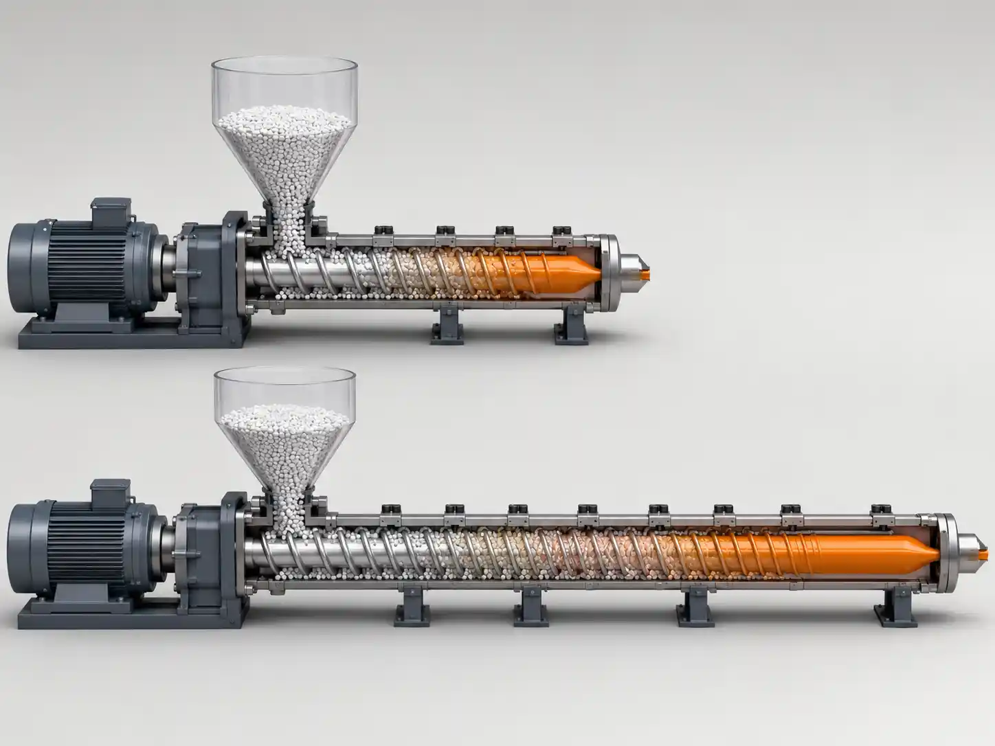
That sequence is why one number on the extruder datasheet matters more than buyers usually assume: the L/D ratio, the flighted length of the screw divided by its diameter. A 90 mm screw at 30:1 carries roughly 2,700 mm of flighted length; the same screw at 24:1 carries about 2,160 mm. Longer is routinely sold as better. In cable work it often is not - because the screw does not just deliver output, it delivers a melt at a particular temperature and consistency, and the forming stage downstream was designed around that melt.
This guide covers what L/D does at each extrusion station in a cable plant, how it interacts with the forming tooling, and where extra length stops helping and starts costing you product.
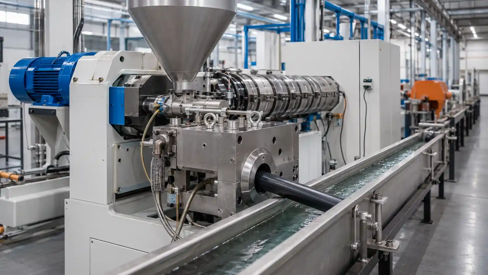
Where extrusion and forming happen on a cable line
A cable plant does not have one extrusion process. It has several, sharing little except the word "extruder":
- Secondary coating (loose tube). A small extruder forms a PBT tube around gel-filled or dry-blocked fibres, at high line speed and very tight dimensional tolerance.
- Tight buffering. A very small extruder applies a thermoplastic buffer directly over 250 µm coated fibre to produce 900 µm indoor fibre.
- Inner sheath and bedding. A medium extruder applies polyethylene over the stranded core before armouring.
- Outer sheathing and jacketing. The largest extruder on the line applies PE, LSZH or PVC over the finished core - over steel tape, corrugated armour or aramid, sometimes as a figure-8 profile with an integral messenger.
The compounds range from hygroscopic engineering thermoplastics to heavily filled halogen-free formulations. Outputs range from a few kg/h to several hundred. Specifying one "standard" L/D across a fiber optic cable manufacturing line guarantees that most of those stations are running the wrong screw.
What L/D measures, in cable terms
L/D is a shape ratio, not a capacity rating:
- L - the flighted working length of the screw, from the rear of the feed opening to the tip.
- D - the screw diameter, which is what actually sets the output class of the machine.
A 45 mm buffer-tube screw and a 120 mm sheathing screw can both be 30:1 and differ tenfold in output. The 45 mm machine is producing a 2.5 mm tube at 200 m/min; the 120 mm machine is producing a 2 mm wall over a 15 mm core at 40 m/min. Same ratio, entirely different jobs. Diameter and drive power set the throughput ceiling; L/D decides how much room the screw has to melt, homogenise and pressurise the compound before the crosshead takes over and starts forming it.
One structural detail explains most of the confusion. The feed section stays roughly the same length no matter how long the screw is. Every diameter you add goes into melting and metering - into melt quality and pressure - not into feeding. So the question is never "do I want more length"; it is "does this compound, at this output, need more melting or more metering".
Why extruders got longer, and why cable lines stayed short
A 20:1 machine was normal into the early 1960s and 24:1 counted as a long screw. Since then the general market has drifted upward, to the point that 30:1 to 36:1 is now treated as the commercial default on general-purpose single-screw machines. That is a common offering from machine builders, not a formal standard from any standards body - a distinction worth holding onto when a quotation describes 36:1 as "industry standard".
Engineering references stayed more conservative, describing single-screw L/D as typically 20 to 30, with 24 the most common value, and recent peer-reviewed work notes that the push toward 30:1 and beyond has been driven mainly by throughput and mixing demands, with residence time as the price paid.
Cable extrusion largely did not follow that drift, for a reason specific to the industry: the extruder does not set the production rate - the cable does. Output equals line speed multiplied by the cross-sectional area of the layer being applied, and both of those are fixed by the product and by the slowest element on the line, which is usually the cooling trough, the capstan, the caterpillar or the stranding upstream. A sheathing extruder typically runs well below its capability. Length bought to chase throughput you will never reach is length that only adds residence time to a compound that would rather not have it.
What extra length actually buys on a cable line
- Melting capacity - a fully melted, thermally uniform melt. On a loose tube line this shows up directly as wall thickness consistency and roundness; unmelted material or a temperature gradient across the melt becomes ovality and eccentricity in a tube with a 0.2 mm wall.
- Pressure generation - head pressure without excessive screw speed. This matters most at the two small stations: tight buffering, where the die is very restrictive, and buffer tube extrusion, where pressure stability translates straight into diameter stability.
- Homogenisation - even distribution of additives. This is the strongest argument for length on an outdoor sheathing line, where 2–3% carbon black has to be dispersed uniformly or the UV protection on a 30-year aerial cable becomes a lottery.
- Venting - a decompression and vent zone for moisture and volatiles, which contributes nothing to output but consumes real length.
Where the output gains stop
Adding L/D does not raise output indefinitely, because the limit usually sits upstream in the feed section - and both failure modes show up in cable plants:
- Small screws are limited by torque. On a 45 mm buffer-tube screw, the channel can only be deepened so far before the root diameter is too thin and the screw risks torsional failure. Buffer tube lines run into this before they run into melting length.
- Large screws are limited by feeding. As the feed channel is deepened, the screw stops filling reliably and output flattens regardless of length. Highly filled LSZH pellets, with their different bulk density and surface friction, feed differently from natural PE - one reason a screw that works on a PE sheathing line can disappoint on the same machine running a halogen-free compound.
Solids conveying depends on bulk density, pellet shape and friction against the barrel versus the screw, which is why a grooved feed section with a properly cooled feed throat can keep output climbing where a smooth barrel plateaus. If a supplier offers a longer machine as the cure for low output, establish first whether the constraint is melting length at all, or feeding, torque, drive power - or simply the line speed the cable allows.
From screw to crosshead: where extrusion becomes cable forming
The screw hands the melt to a crosshead die, and everything the screw did well or badly is inherited by the forming stage.
- Tooling type. Loose tube and most jacketing use tubing tooling, where the melt leaves the die as an annulus and draws down onto the core - essential when the melt must not touch the fibres. Pressure tooling, where melt meets the core inside the die, is used where adhesion is required. Tubing tooling generally runs at lower head pressure than pipe or profile extrusion, which quietly weakens the case for a long metering section on a sheathing screw.
- Draw-down. The annulus is drawn down to final dimensions between die exit and cooling. That draw depends on melt strength, and melt strength falls as melt temperature rises. A screw running hotter than the process was designed for gives a melt that sags, goes oval and loses wall concentricity - a forming defect with an extrusion cause.
- Vacuum and cooling. On loose tube lines, crosshead vacuum controls tube diameter and prevents collapse, and the cooling trough profile sets the shrinkage behaviour of the finished tube. Both were tuned around a specific melt temperature arriving at the die.
This is why L/D cannot be evaluated as a machine specification in isolation. On a cable line it is a forming parameter: it sets the thermal state of the melt at the point where geometry gets locked in.

L/D by station
Loose tube (secondary coating)
PBT is the dominant loose tube material for its stiffness, chemical resistance and dimensional stability - and it is hygroscopic, hydrolysing in the melt if it is not dried to a very low residual moisture, typically specified in hundredths of a percent. That gives two routes: dry thoroughly and run a single-stage screw, or vent and pay for the length.
Most loose tube lines dry, which keeps a 25:1 to 30:1 single-stage screw viable on a small diameter. The deciding constraint at this station is thermal rather than volumetric, because excess fibre length is created in the cooling profile, as the tube shrinks onto fibres that were coupled to it while still warm. Published work on EFL control puts typical requirements anywhere from zero to a fraction of one percent depending on cable design, achieved by managing quench point and dwell time. A screw that delivers melt hotter than the design point moves the entire cooling window and drags EFL and post-extrusion shrinkage with it - which is why excess length control belongs in the screw specification conversation, not only in the cooling-trough conversation.
Tight buffering
Tight buffering applies a thermoplastic layer directly over 250 µm coated fibre at very low output through a restrictive die, with an acrylate coating underneath that has little thermal tolerance. Length here buys melt quality and pressure stability rather than throughput - but it also buys residence time on a compound sitting millimetres from a fibre that will not forgive a hot spot. Short, well-profiled screws are the norm. The contrasting demands of tight-buffered and loose-tube constructions are the clearest illustration of why one screw specification cannot cover a plant.
Polyethylene sheathing
The most tolerant station. MDPE and HDPE have a wide processing window, and tubing tooling at modest head pressure means a long metering section returns less than the datasheet implies. Where length earns its keep is dispersion - carbon black and UV or anti-rodent additives must be distributed evenly through the wall. A barrier or mixing screw at 25:1 to 30:1 generally achieves that better than a longer general-purpose screw. Where a melt pump is fitted for diameter stability, the pressure argument for 36:1 largely disappears.
LSZH and flame-retardant sheathing
The least tolerant station on the line. Low-smoke zero-halogen compounds carry very high mineral filler loadings, and aluminium trihydrate begins releasing water not far above normal polyolefin processing temperatures - that decomposition is precisely the mechanism that makes the compound flame-retardant, and precisely what must not happen inside the barrel. High viscosity, high shear heating and low thermal headroom combine into a narrow window.
This is the clearest case in cable extrusion where less L/D is better: shorter screws, low-shear profiles, generous cooling, conservative screw speeds. Comparing the processing behaviour of PE, LSZH and PVC sheathing materials is a far more productive starting point for screw selection than comparing L/D figures across quotations.
Recommended L/D ranges by station
| Station | Typical single-stage L/D | What decides it |
|---|---|---|
| Tight buffering (900 µm) | 20:1 – 25:1 | Very low output, restrictive die, low thermal tolerance of the fibre coating. |
| Loose tube (PBT, dried) | 25:1 – 30:1 | Dimensional tolerance and EFL stability; drying removes the need to vent. |
| Loose tube (vented, undried) | 30:1 – 36:1, two-stage | Roughly 4–6 D consumed by decompression and venting. |
| PE inner sheath / bedding | 24:1 – 30:1 | Wide processing window; screw profile matters more than length. |
| PE outer sheath | 25:1 – 30:1 | Carbon black dispersion and output stability; barrier or mixing profile preferred. |
| LSZH / FR sheath | 20:1 – 26:1 | Melt-temperature ceiling set by filler decomposition, not by throughput. |
Treat these as starting points for a conversation with a screw designer, not as specifications. Diameter, channel depths, compression profile, screw speed range and drive torque all move the answer.
Venting versus drying on a cable line
Vented two-stage screws are the strongest case for a long L/D anywhere in a cable plant. The decompression and vent zone - commonly quoted at roughly 4 to 6 diameters - does no melting and generates no pressure; it exists to pull moisture and volatiles out of the melt before the metering section repressurises it for the crosshead.
The familiar rule of thumb is that a 30:1 two-stage screw is needed to match the output of a 24:1 single-stage screw. That holds only when the two share the same diameter, screw speed, drive package, material, channel depths, die pressure and melt-temperature ceiling. It is a planning allowance, not a formula.
For most cable plants the economics favour drying. PBT and many filled compounds pick up moisture in storage, and a well-run dryer is cheaper than six diameters of barrel, screw, heating and floor space - plus it avoids the vent-flooding problems that a partly filled second stage can create on a line where output is dictated by line speed rather than by the operator.
When a longer screw damages the cable
Excess length shows up first as melt temperature, and in cable extrusion melt temperature is a product specification issue, not a comfort issue:
- Degradation and colour shift in the sheath, with loss of environmental stress crack resistance in PE.
- Additive failure - UV stabiliser and flame-retardant performance depend on the compound not having been cooked on the way to the die.
- Plate-out on the crosshead and die land, which becomes die lines, surface defects and diameter drift over a long production run.
- Loss of melt strength at the draw-down, producing ovality and wall eccentricity that no tooling adjustment will fully correct.
- EFL and shrinkage drift on the loose tube line, because the cooling window was designed around a melt temperature you are no longer delivering.
Once melt temperature is the binding constraint, output measured at the die stops meaning anything - which is where barrel and melt temperature control stops being a setting on a panel and becomes a limit built into the machine you bought.

Two mechanisms deserve to be named explicitly:
- An over-long transition section can slow melting rather than accelerate it. On an easy-melting polyolefin, spreading compression over too many diameters compresses the solid bed too gradually, thickens the melt film and lowers the shear rate that drives melting, sometimes ending in solid-bed breakup. The effect is real but geometry-dependent - it argues for matching melting length to the resin, not for short screws in general.
- Melt pumps have changed the pressure argument. Where a gear pump handles head pressure and output smoothing, the screw no longer has to build discharge pressure on its own, and a long metering section becomes much less valuable.
How to choose L/D for a cable extruder
- Start from line speed and layer geometry. Output in kg/h is a consequence of the cable, not a target you pick. Size diameter and drive to that, then discuss length.
- Characterise the compound. Viscosity at process shear rates, degree of shear thinning, filler loading, crystallinity, bulk density and above all the melt-temperature ceiling. Resin suppliers publish this, and some state a minimum L/D outright, as Arkema does in its wire and cable processing guidelines.
- Bring the crosshead into the conversation. Tooling type, die pressure and draw-down ratio determine how much metering length is actually useful.
- Decide drying versus venting. If the station must vent, add roughly 4–6 D and re-examine the total cost.
- Check what dispersion the layer needs. Carbon black, flame retardants and UV packages may call for a barrier or mixing profile rather than raw length.
- Ask how often the compound will change. A dedicated sheathing line can be optimised tightly; a line running PE this year and LSZH next benefits from flexibility, and that is the legitimate argument for a longer screw.
- Confirm on the machine. Trial at production line speed and measure melt temperature, head pressure, motor load, diameter and ovality - and on loose tube, EFL - before signing off.
Signs the screw length is wrong
Too long for the process:
- Melt temperature well above setpoint at normal line speed, with barrel zones in cooling for most of the run.
- Discoloration, gels or plate-out that worsen with residence time, particularly after a line stop.
- EFL or post-extrusion shrinkage drifting from the recipe with no change to the cooling trough.
- Ovality or sagging at draw-down that improves when screw speed is reduced.
Too short for the process:
- Unmelted particles, gels or visibly poor carbon black dispersion in the sheath.
- Pressure and output surging, appearing as diameter variation down the length of the drum.
- Head pressure unreachable without running the screw faster than the compound tolerates.
- Wall thickness variation that does not respond to tooling, vacuum or line-speed adjustment.
These symptoms overlap with screw profile, crosshead tooling and temperature-profile faults, so confirm the diagnosis before concluding the machine is the wrong length.
FAQ
Q: What Does L/D Mean In Cable Extrusion?
A: It is the flighted length of the extruder screw divided by its diameter, written as a ratio such as 24:1 or 30:1. It describes the proportions of the screw, not the capacity of the machine or the output of the line.
Q: What L/D Is Used For Loose Tube Extrusion?
A: Dried PBT on a single-stage screw is commonly handled at 25:1 to 30:1. If the process vents instead of drying, a two-stage screw around 30:1 to 36:1 is needed, because roughly 4 to 6 diameters go to the vent zone.
Q: Is 30:1 Better Than 24:1 For A Sheathing Line?
A: Only if the compound needs the extra melting length, dispersion or pressure. For a heavily filled LSZH jacket with a narrow thermal window, 24:1 with the right profile can produce a better sheath at a lower melt temperature.
Q: Does A Longer Screw Increase Output On A Cable Line?
A: Rarely. Output is set by line speed and layer cross-section, and the line is usually limited by cooling, capstan or upstream stranding. Once feeding, torque or drive power is the limit, extra length adds heat history without adding throughput.
Q: Can A High L/D Cause Polymer Degradation In A Cable Jacket?
A: Indirectly, yes. More length means more shear history and longer residence time; the resulting melt temperature rise drives degradation, colour shift, additive loss and plate-out. The length is not the hazard - the thermal history it produces is.
Q: Does L/D Affect Excess Fibre Length?
A: Not directly, but it affects melt temperature, and melt temperature sets the starting point of the cooling profile in which EFL is created. A screw running hotter than the design point will move EFL and post-extrusion shrinkage even with unchanged cooling trough settings.
Q: How Does A Melt Pump Affect L/D Selection?
A: A gear pump takes over pressure generation and output smoothing, so the metering section no longer has to do that work. Lines with melt pumps can often run shorter screws at lower melt temperature with better diameter control.