





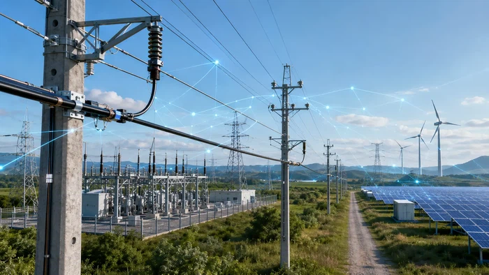
Power grids are expanding, and so is their need for dedicated communication infrastructure. As electricity demand rises - driven by data centers, renewable energy integration, electric vehicles and industrial electrification - utilities face a parallel challenge: building reliable fiber optic routes along power corridors to support grid monitoring, protection signaling, automation and long-distance data transmission.
ADSS (all-dielectric self-supporting) fiber optic cable is one of the primary solutions for deploying fiber along existing overhead power lines without requiring a metallic messenger wire. This article explains when ADSS cable is the right choice for power utility routes, how it compares with OPGW and underground fiber, and what buyers should prepare before requesting a quotation.
Table of Contents
- Why Power Grid Expansion Now Requires Fiber Infrastructure
- ADSS Cable for Power Lines: When Is It the Right Choice?
- ADSS vs OPGW vs Underground Fiber: How to Choose
- Key Design Factors for ADSS Cable on Utility Routes
- When Is AT Sheath Required for ADSS Cable?
- ADSS Cable Quotation Checklist for Buyers
- FAQ
Why Power Grid Expansion Now Requires Fiber Infrastructure
Grid modernization is no longer limited to adding generation capacity or upgrading transmission lines. Utilities must now deploy communication networks that support real-time monitoring, protection relay coordination, SCADA systems, fault detection and distributed energy resource management across substations, feeders and control centers.
The scale of this shift is significant. According to the International Energy Agency's Electricity 2026 report, global electricity demand is forecast to grow at an average annual rate of 3.6% through 2030, with data centers alone expected to account for nearly half of U.S. demand growth over that period. This load growth - combined with the integration of solar, wind, battery storage and distributed generation - creates operational complexity that older communication systems were not designed to handle.
Fiber optic cable is well suited for utility communication because it offers high bandwidth, low latency and immunity to electromagnetic interference from adjacent power conductors. The question for many utilities is not whether they need fiber along their power corridors, but which cable type and deployment method fits each route.
ADSS Cable for Power Lines: When Is It the Right Choice?
ADSS stands for all-dielectric self-supporting. The cable contains no metallic elements - no ground wire, no steel messenger, no conductive armor. It hangs between poles or towers under its own tension, supported by aramid yarn strength members and a robust outer sheath. This design makes ADSS cable electrically transparent to power conductors, which is a significant advantage for installation on or near energized power lines.
ADSS cable is typically a strong fit in the following scenarios:
- Distribution and sub-transmission routes (typically below 110 kV) where existing pole lines are available
- Rural power corridors where trenching for underground fiber would be prohibitively expensive or slow
- Substation-to-substation communication links using existing overhead right-of-way
- Smart grid monitoring networks that need fiber along medium-voltage feeders
- Combined utility and broadband backhaul routes in remote areas
ADSS is less suitable when the route involves very high voltage lines (above 150–220 kV depending on pollution level) without appropriate sheath protection, or when the route has no existing pole infrastructure and underground duct is readily available. Before choosing ADSS, buyers should first confirm whether the route uses distribution poles, transmission towers or mixed corridors - and what the voltage environment looks like at the planned attachment point.
For a broader view of aerial fiber optic cable options beyond ADSS, including figure-8 and lashed designs, Hengtong's aerial cable category covers the main structural types.
ADSS vs OPGW vs Underground Fiber: How to Choose
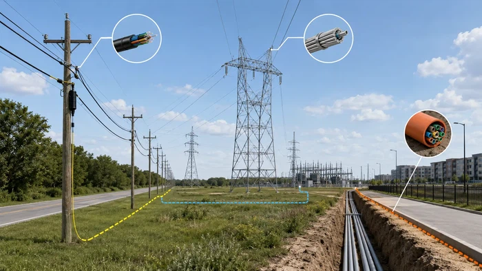
Utility fiber route planning often involves comparing three main deployment methods. Each has distinct strengths, and many grid communication projects use more than one type across different route segments.
| Factor | ADSS Cable | OPGW (Optical Ground Wire) | Underground Fiber Cable |
|---|---|---|---|
| Structure | All-dielectric, self-supporting, no metallic parts | Fiber inside a ground wire that replaces the existing shield wire | Duct, direct burial or armored cable below ground |
| Typical voltage range | Best below 110 kV; usable up to 220 kV with AT sheath and careful placement | Designed for high-voltage transmission lines (110 kV and above) | Not voltage-dependent; separated from power conductors |
| Installation requirement | Can be added to existing poles without power outage in many cases | Requires power outage for shield wire replacement | Requires trenching, boring or existing duct infrastructure |
| Civil works | Minimal - uses existing overhead infrastructure | Minimal - replaces existing ground wire | Significant - trenching, conduit, backfill, restoration |
| Lightning protection | No built-in lightning protection | Serves as shield wire and provides lightning protection | Not applicable |
| Best fit | Distribution routes, rural corridors, broadband backhaul, add-on fiber to existing poles | High-voltage transmission routes where ground wire replacement is planned | Urban areas with duct, routes needing maximum physical protection |
A common decision framework: if the route is a high-voltage transmission line and the utility plans to replace the existing ground wire, OPGW is often the most cost-effective choice because it combines lightning protection with fiber in a single cable. If the route is a distribution or sub-transmission corridor with existing poles, ADSS allows fiber to be added without a power outage and without replacing any existing conductor. If the route passes through urban areas with available duct, underground fiber optic cable may offer better long-term physical protection.
In practice, a single grid communication project may use OPGW on transmission segments, ADSS on distribution segments, and duct cable through urban sections. The choice should be made segment by segment based on voltage, pole availability, right-of-way, construction access and maintenance requirements.
Key Design Factors for ADSS Cable on Utility Routes
Selecting ADSS cable by fiber count alone is a common procurement mistake. The cable must be engineered for the specific route, and two routes with the same fiber count can require very different cable structures. The following factors drive the design.
Span Length and Mechanical Load
Span length is the single most important variable in ADSS cable design. The cable must support its own weight plus wind load, ice load and installation tension across each span without exceeding allowable sag or long-term creep limits. A 100-meter span on flat terrain between distribution poles and a 500-meter span crossing a river valley require fundamentally different strength member designs, cable diameters and hardware ratings.
Buyers should provide the average span, maximum span and any special crossing spans (river, highway, valley) before requesting a quotation. If the maximum span is not confirmed, the supplier may quote a structure that cannot match actual tension or sag requirements - leading to re-specification and project delay.
Fiber Count and Future Capacity
Common fiber counts for utility ADSS cables range from 12 to 144 fibers, with higher counts available for backbone routes. The right count should consider current communication demand plus reserve capacity for future smart grid sensors, substation upgrades, distributed energy monitoring or broadband sharing. For long-distance utility trunk routes, G.652D single-mode fiber is the standard choice. Bend-insensitive fibers such as G.657A1 or G.657A2 may be specified for routes with tighter bending at hardware attachment points.
Jacket Material
Standard ADSS cables use PE (polyethylene) or HDPE outer sheaths, which are adequate for most distribution-voltage aerial routes. In higher electric field environments, an AT (anti-tracking) sheath is required - this is discussed in detail in the next section. Jacket selection should also consider UV exposure, pollution, temperature range and local environmental conditions.
Installation Hardware
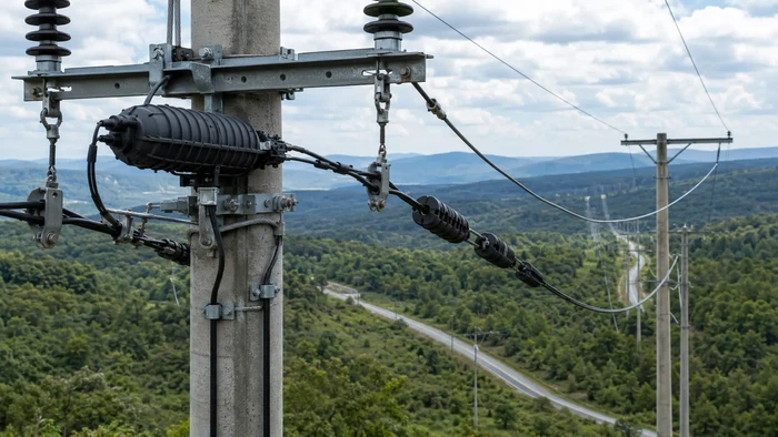
ADSS cable performance depends as much on hardware as on the cable itself. Suspension clamps support the cable at intermediate poles, tension (dead-end) clamps anchor the cable at termination and angle poles, and vibration dampers reduce aeolian vibration fatigue over long spans. Splice closures, down-lead clamps and pole brackets complete the installation. All hardware should be matched to the cable diameter, span length and installation tension - mismatched hardware is a common cause of premature cable damage.
Testing and Acceptance
For utility-grade ADSS cable, buyers should specify testing requirements that align with recognized standards. The IEC 60794 series defines test methods for optical fiber cables, covering mechanical properties (tensile strength, crush resistance, impact), environmental properties (temperature cycling, water penetration, UV aging) and optical performance (attenuation, bandwidth). Testing requirements should be confirmed during the quotation stage, not after production.
Hengtong provides detailed information on fiber optic cable testing procedures and quality verification for communication cable projects.
When Is AT Sheath Required for ADSS Cable?
One of the most frequent technical questions in ADSS cable procurement is whether the cable needs an AT (anti-tracking) sheath. The answer depends on the electric field environment at the cable's attachment point - not just the nominal voltage of the power line.
When ADSS cable is installed near high-voltage conductors, capacitive coupling between the power lines and the cable surface can induce a voltage gradient along the cable. In humid or polluted conditions, moisture on the cable surface creates a conductive film. As parts of this film dry unevenly, "dry bands" form where the voltage drop concentrates, causing localized arcing. Over time, this dry-band arcing degrades the cable sheath, eventually exposing the strength member and causing cable failure. Research published in IEEE Transactions on Power Delivery and IEEE Transactions on Dielectrics and Electrical Insulation has documented this mechanism extensively.
AT sheath materials contain additives that resist the surface degradation caused by these discharges. As a general guideline:
- For routes below 35 kV, standard PE or HDPE sheath is usually sufficient
- For routes between 35 kV and 110 kV, the need for AT sheath depends on pollution level, humidity, cable attachment position and span configuration
- For routes above 110 kV, AT sheath is strongly recommended, and careful attention must be paid to cable placement relative to phase conductors
Pollution level matters as much as voltage. A 66 kV line in a clean, dry environment may not require AT sheath, while a 33 kV line in a coastal or industrial area with heavy pollution might. Buyers should provide the voltage level, pollution classification (if available) and attachment point position when requesting a quotation so the supplier can recommend the appropriate sheath.
Planning ADSS Cable Procurement for Grid Projects
In grid communication projects, cable procurement is sometimes treated as a late-stage purchasing task. This approach creates risk. ADSS cable design depends on route-specific mechanical, environmental and electrical factors that take time to confirm. If span data, voltage environment or sheath requirements change after the order is placed, the result is re-specification, production delays and potential cost increases.
Early cable planning helps buyers and engineers confirm whether ADSS, OPGW, duct cable or direct burial cable is the right fit for each route segment before committing to procurement. It also allows time to verify whether cable and hardware can be quoted together, whether reel lengths match the construction plan, and whether the cable can meet required testing standards.
For projects that need to evaluate route-specific ADSS cable options, visit Hengtong's ADSS fiber optic cable page or contact the engineering team with your span, fiber count and route details.
FAQ: ADSS Cable For Power Grid And Utility Fiber Routes
Q: Can ADSS Cable Be Installed On High-Voltage Power Lines?
A: ADSS cable can be installed near high-voltage power lines, but the voltage environment and pollution level at the attachment point determine whether AT sheath is required and where the cable should be positioned relative to phase conductors. For routes above 110 kV, AT sheath is strongly recommended. For routes above 220 kV, detailed electric field analysis and careful cable placement are essential to avoid dry-band arcing damage.
Q: What Is The Difference Between ADSS Cable And OPGW?
A: ADSS is an all-dielectric cable that attaches to existing poles or towers as an additional cable. OPGW is a composite cable that replaces the existing ground (shield) wire on transmission lines, combining fiber optic cores with metallic ground wire function. ADSS is typically used on distribution and sub-transmission routes; OPGW is used on high-voltage transmission lines where ground wire replacement is planned.
Q: What Span Length Should I Provide For An ADSS Cable Quotation?
A: Provide both the average span and the maximum span on the route, measured in meters. If the route includes special crossings (river, highway, valley), note those separately. Span length is the primary driver of ADSS cable mechanical design - without it, the supplier cannot recommend the correct cable structure or hardware.
Q: When Is AT Sheath Required For ADSS Cable?
A: AT (anti-tracking) sheath is required when the cable will be installed in an environment where dry-band arcing is a risk. This depends on the voltage at the attachment point, pollution level and humidity. As a general guide, AT sheath is usually not needed below 35 kV, should be evaluated between 35–110 kV depending on conditions, and is strongly recommended above 110 kV.
Q: What Information Is Needed For An ADSS Cable Quotation?
A: At minimum, provide fiber count, span length (average and maximum), voltage environment and total route length. Additional details that improve quotation accuracy include fiber type, route environment, wind/ice load data, hardware requirements, testing standard and delivery country.
Q: Can ADSS Cable Support Rural Broadband Projects?
A: Yes. ADSS cable can be installed along existing power distribution poles, making it a practical option for extending broadband backhaul to rural areas where underground construction would be too expensive or slow. Many rural fiber projects combine utility communication and broadband backhaul on the same ADSS cable route.