






How AI GPU Clusters Drive the Need for High Density Fiber Optic Cable
AI-driven GPU clusters demand far more fiber density in modern data centers today. Because scalable 400G, 800G, and 1.6T network systems need room to grow, high-density fiber optic cabling has become a core requirement. Standard cloud setups used to run virtual machines on general-purpose servers, but modern machine learning workloads require massive parallel processing instead. This fundamental shift completely alters physical network design, forcing data center architects to fit an unprecedented number of fiber cores into extremely tight physical spaces. In this comprehensive guide, we will analyze the physical limits of legacy cabling, explore the structural engineering behind advanced optical solutions, and review the exact installation rules that govern high density fiber optic cable across next-generation artificial intelligence facilities and modern enterprise data center interconnect architectures.
Why AI data centers require exponentially more fiber
Data traffic inside modern facilities has turned completely inside out. Traditional cloud environments primarily handled North-South traffic, which simply means data moved from an outside user down to a local server and back out again. Network engineers could easily use a 3:1 or 4:1 oversubscription ratio at the switch level because they knew most servers would never send heavy data streams at the exact same moment.
AI model training breaks this old design completely. When training a large language model, thousands of GPUs must run side by side while constantly trading massive sets of calculation parameters with one another. This workload generates intense East-West traffic that stays entirely within the facility walls, rushing continuously from chip to chip. To ensure expensive compute hardware never sits idle waiting on network traffic, these modern clusters require a strict 1:1 non-blocking topology. Every single compute node must be able to talk to every other node at full wire speed without any delay.
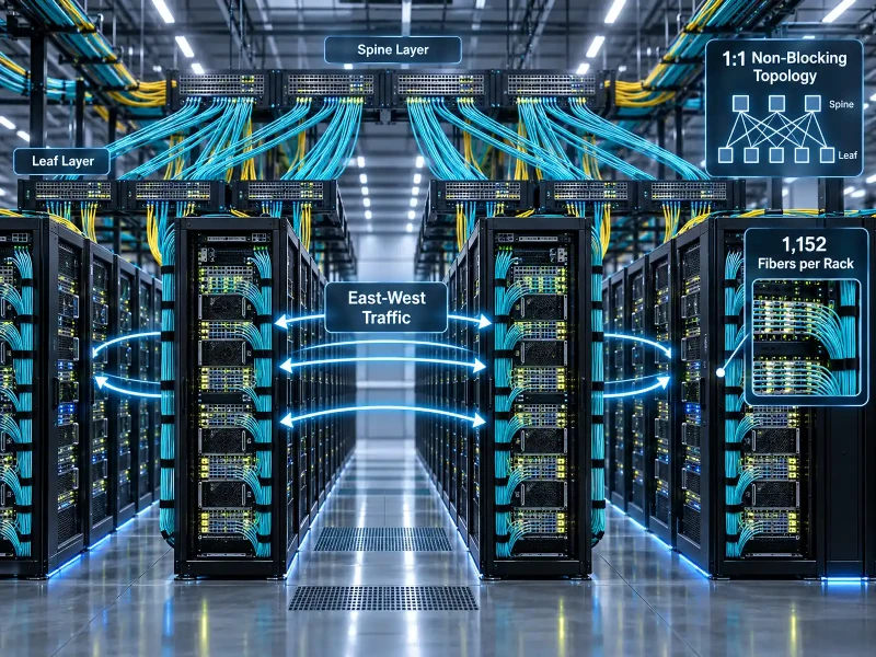
This shift creates a massive surge in physical fiber links across the data hall. While a standard cloud server rack might need only a few dozen fiber strands running to the spine switch, a high-density AI cluster scales that number up dramatically. In fact, the fiber count fed to a single AI server rack (NVIDIA NVL72) reaches 1,152 fibers.
Connecting all of these racks together requires an optical network that expands easily without filling up every physical pathway. Right now, the industry is managing a 330% bandwidth growth for data center connectivity (2020–2024). This huge jump in data volume creates serious power and heat challenges across the building. Copper twinax cables cannot carry high-frequency signals very far because of severe electrical signal loss and heavy power draw. When running at 400G or 800G speeds, copper only reaches a few meters, forcing facilities to place optical transceivers right next to the processors.
This extreme compute density directly impacts overall utility power across the country. The US data center electricity consumption reached 176 terawatt-hours as of 2023. As companies build out larger non-blocking optical networks and add the necessary cooling gear, the projected US data center electricity consumption is 6.7% to 12% as of 2028. Moving data with light rather than electricity helps facilities stay within their thermal and electrical budgets, which directly creates the need for thousands of optical strands down every single row.
The physical bottlenecks of scaling to high speed networks
Upgrading modern switches to run at 400G, 800G, or 1.6T speeds relies heavily on parallel optics. Instead of sending one signal down a single pair of strands, optical transceivers like the 400GBASE-SR8 or 800GBASE-DR8 split that signal across eight parallel optical paths. This design means one transceiver port needs 16 individual fiber strands (eight to transmit and eight to receive) instead of the standard two strands used in older networks. When a single network switch packs 64 of these high-speed ports, the sheer physical size of all those cables quickly creates a major space problem.
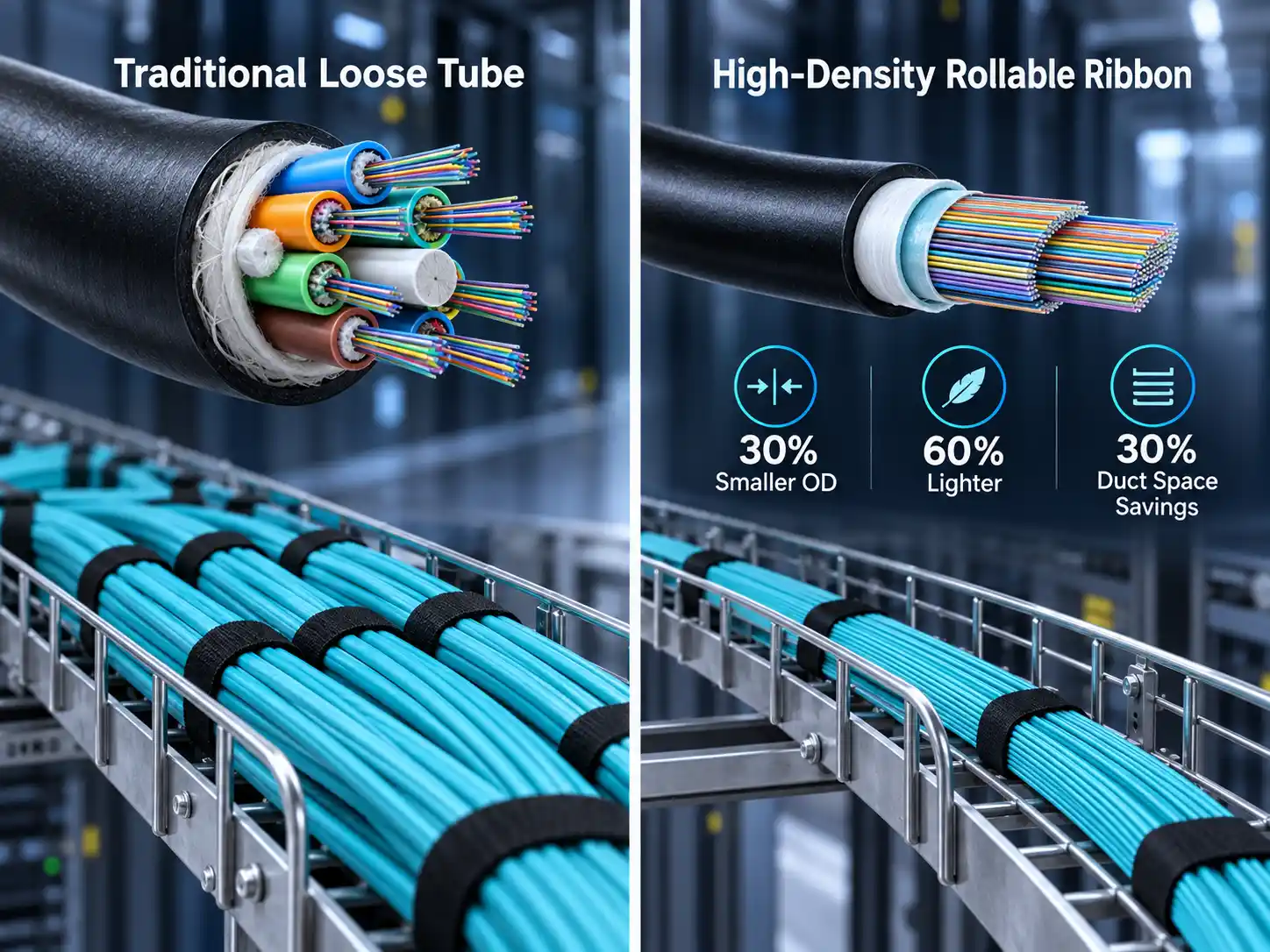
Older fiber lines rely on loose tube construction. In these traditional cables, individual 250-micron coated fibers sit loosely inside stiff plastic buffer tubes that wind around a central fiberglass rod. Engineers fill the empty gaps with water-blocking gel or dry swellable tape, add aramid yarn for pulling strength, and seal everything inside a thick polyethylene jacket.
These cables work well outdoors, but their bulky round design wastes a massive amount of cross-sectional space indoors. When network engineers try to scale standard loose tube cables to hold thousands of optical strands, the outer cable size becomes much too large. Standard pathways inside a facility run through 2-inch or 4-inch conduits. Even though conduit volume grows with the square of its radius, packing stiff round tubes inside round conduit pipes leaves a lot of empty, unusable space. Trying to pull a traditional 1728-fiber loose tube cable through a standard 2-inch innerduct is physically impossible because of tight spaces and friction.
This congestion spills out of the underground pipes and straight onto the data center floor. When thick, heavy cables enter the room, workers must route them through overhead cable trays. The raw weight of traditional high-strand cables can easily exceed the structural load limits of standard ceiling drop-rods. Furthermore, bulky bundles block airflow through cold aisle containment systems, creating hot spots that force cooling units to work harder and degrade overall Power Usage Effectiveness.
At the patch panels, space limits become even more difficult to manage. Terminating thousands of individual loose fibers requires dozens of large splice trays. In a non-blocking AI fabric, patch panels must support incredible densities so any GPU can connect directly to any other GPU. Today, the maximum fiber density in a single rack reaches 41,472 patched fibers. If technicians tried to build this setup using standard 250-micron loose tube cables, they would need multiple floor racks just to hold the patch trays, taking up valuable floor space that should hold compute servers instead.
How high density cabling solves space and weight issues
To move past the limits of loose tube cables, optical manufacturers developed a completely new approach to cable manufacturing. The industry first established a clear baseline for high-capacity cabling, where the Ultra-High Fiber Count (UHFC) cable definition is > 576 fibers. To fit this many strands into a manageable outer jacket, engineers had to shrink the physical dimensions of the coated glass.
A standard optical fiber uses a 9-micron core surrounded by a 125-micron glass cladding, which keeps light trapped inside through total internal reflection. Because this core glass size is an international standard, engineers cannot shrink it without breaking compatibility with existing network hardware. However, they can easily trim down the outer protective layers. Standard fibers use a dual-layer UV-cured acrylate coating that creates a total strand diameter of 250 microns. By using a tougher, more compact resin, the reduced buffer coating size for high-density cables is 200 microns.
Shaving 50 microns off a tiny fiber coating might sound minor, but the space savings add up very quickly. Because the area of a circle scales with the square of its radius, dropping the strand diameter from 250 to 200 microns reduces its cross-sectional area by roughly 36%. When you bundle thousands of these smaller strands inside a single jacket, the overall space savings are dramatic.
The second major engineering breakthrough replaces stiff flat ribbons with flexible rollable ribbons, which are also called spiderweb ribbons. Traditional flat ribbons bind 12 fibers together in a continuous solid plastic strip. Because these flat ribbons can only stack like wooden boards, they form stiff rectangular blocks that fit poorly inside round jackets. Rollable ribbon designs apply tiny glue dots intermittently along the 12 fibers. This lets the ribbon open completely flat for mass fusion splicing, while also allowing it to roll into a compact round bundle inside the cable.
Combining 200-micron fibers with rollable ribbons delivers huge physical advantages. For instance, plant engineers see a 30% outer diameter reduction for 200-fiber cable when compared to older designs. Eliminating extra plastic fillers and heavy gels also delivers a 60% weight reduction for 200-fiber cable. Because these thinner cables bend easily around tight corners in underground ducts and overhead trays, facilities achieve 30% duct space savings using high-density optical cable.
| Metric | Traditional Cable (250µm) | High-Density Cable (200µm) | Improvement |
|---|---|---|---|
| Buffer Coating Diameter | 250 microns | 200 microns | 20% diameter reduction |
| Duct Space Utilization | Rigid loose tube | Flexible rollable ribbon | 30% duct space savings |
| Outer Diameter (200-fiber) | Baseline | Compacted | 30% outer diameter reduction |
| Cable Weight (200-fiber) | Baseline | Lightweight | 60% weight reduction |
Splicing and identifying ultra high fiber count cables
Installing ultra-high fiber count cables creates a real challenge for field technicians, who must identify and terminate thousands of tiny strands without making costly mistakes. In standard 144-fiber cables, technicians simply follow a standard 12-color code (Blue, Orange, Green, Brown, and so on) to track individual tubes and fibers. If any wire gets mixed up, a technician can shine a visible red laser with a Visual Fault Locator into the line to confirm the connection.
When a single cable holds thousands of strands, using a red laser locator becomes completely impractical. Light bleeds easily across tightly packed 200-micron fibers, making it hard to tell which specific core is glowing. On top of that, the standard 12-color sequence repeats hundreds of times inside a UHFC jacket. To fix this, manufacturers use a clocked layout paired with printed markings directly on the ribbons.
In a clocked design, the interior of the cable is split into clear sections, using a colored binder yarn to mark the starting point at the "12 o'clock" position. Technicians simply count clockwise from this reference marker to locate the right bundle. Inside the bundle, each rollable ribbon features a printed dot-dash code on its matrix binder. By reading these printed dots and dashes, a technician can quickly identify ribbon number 144 out of 288 without having to shine a light down the line.
Once the right fibers are isolated, the termination work must move quickly. If a technician spliced a 3,456-fiber cable one strand at a time with a single-fiber machine, finishing that single joint would take several weeks of nonstop manual labor. High-density fiber jobs solve this problem by using mass fusion splicing instead.
Mass fusion splicers weld 12 fibers in a single step. First, the technician removes the matrix coating using a thermal stripper heated to approximately 100 degrees Celsius, which softens the plastic without scratching the delicate 125-micron silica glass underneath. Next, the 12-fiber ribbon goes into a high-precision multi-fiber cleaver to ensure every glass end is cut at a perfect right angle. Finally, the splicer uses fixed v-grooves and dual-axis cameras to align all 12 pairs of fibers before firing an electric arc to melt the glass ends together.
This ribbon-splicing method saves an enormous amount of project time on the job site. Field teams see an 80% reduction in splicing time using 12-fiber mass fusion vs. Single splicing. By pairing easy cable handling with faster splicing tools, contractors achieve a 5 times speed increase in optical cable installation using FREEFORM Ribbon™ Technology.
| Step | Identification & Splicing Process | Best Practice |
|---|---|---|
| 1 | Ribbon Isolation | Utilize the clocked core design to locate the reference binder, then read the dot-dash code on the ribbon matrix. |
| 2 | Coating Stripping | Use a thermal stripper set to 100 degrees Celsius to remove the 200-micron coating from all 12 fibers simultaneously. |
| 3 | Precision Cleaving | Seat the ribbon in a multi-fiber cleaver to achieve a 90-degree end-face across the entire array. |
| 4 | Mass Fusion Splicing | Align the ribbon in the v-groove and execute the 12-fiber electric arc discharge, verifying alignment via the X/Y cameras. |

Calculating pull tension and bend radius for high density pathways
Installing high-density optical lines requires strict attention to physical pulling limits so the delicate glass inside does not suffer hidden damage. Optical fibers carry data through total internal reflection. When a cable bends tighter than its rated limit, the light hits the core-cladding boundary at too steep of an angle, letting optical photons escape out through the cladding. Network engineers call this macrobending loss.
Microbending loss is an even bigger risk in high-density installations. If an installation crew pulls a cable with too much force, the internal fibers get crushed against the outer jacket and the central strength members. This pressure creates microscopic bends along the length of the glass. Even after the pulling tension stops, these tiny deformations remain in the glass, creating optical signal loss that technicians only detect once the network turns on.
To build safe pathways, engineers must check the exact outer diameter of the cable they plan to install. For reference, the diameter of 1728-fiber RocketRibbon™ cable is 25mm (~1 inch). Step up to the next size, and the diameter of 3456-fiber RocketRibbon™ cable is 32mm (~1.3 inches).
These cable sizes determine the required width of conduit sweeps and pull boxes along the route. As a standard mechanical rule, the minimum bend radius under tension during pulling is 20 times cable diameter. When pulling a 32mm 3456-fiber cable through a duct, all conduit bends and pulling wheels must maintain a curve radius of at least 640mm so the fibers do not get crushed under load. After the cable is seated in place and the tension is gone, the minimum long-term bend radius after installation is 10 times cable diameter, which lets technicians make tighter turns inside patch enclosures.
Engineers generally recommend keeping maximum pulling tension below 600 lbs for typical campus and indoor data center runs. Pulling beyond this limit risks stretching the aramid yarns past their elastic threshold, which dumps all the physical pulling load straight onto the brittle silica glass. To minimize friction and keep pulling tension safe, technicians must carefully manage conduit fill levels. As a best practice, straight runs should not exceed a 40% fill ratio, while complex pathways with multiple turns must stay below a 25% fill ratio. Crews should always use a breakaway swivel matched to the cable rating so the winch disconnects before the glass sustains damage.
| Cable Type | Outer Diameter | Minimum Bend Radius (Pulling) | Minimum Bend Radius (Installed) |
|---|---|---|---|
| 1728-fiber RocketRibbon™ | 25mm (~1 inch) | 500mm | 250mm |
| 3456-fiber RocketRibbon™ | 32mm (~1.3 inches) | 640mm | 320mm |
DCI pricing versus DWDM architectures
When linking separate data halls across a campus or across a city, network architects must carefully design their Data Center Interconnect routes. Digging underground trenches between buildings used to be very expensive, so data center operators historically ran low-strand cables and used Dense Wavelength Division Multiplexing to squeeze more data onto those few fibers. DWDM systems use specialized lasers and optical filters to combine dozens of different colors of light onto a single pair of strands.
However, DWDM transceivers and multiplexing chassis cost a lot of money, consume significant power, and add latency to the network connection. Because distributed AI workloads need the absolute lowest latency and huge parallel bandwidth, DWDM can easily become a major cost and performance bottleneck.
Modern hyperscalers avoid this issue by putting ultra-high-count fiber into the ground as dark fiber insurance. By installing thousands of raw optical strands on day one, data centers can use simple, low-power grey optics (such as 400G-DR4 or 800G-DR8) that run without complex multiplexing hardware. The upfront cost of buying extra glass is quickly offset by huge savings on transceiver hardware and lower power bills.
Current factory equipment sets the physical limits for these massive cables. Right now, the maximum fiber count for Ribbon Slotted-Core cables is 6,912 fibers. Picking the best cable size requires balancing the material cost per foot against the future bandwidth needs of the AI cluster.
Here is a breakdown of common deployment sizes and their estimated material costs:
-
1728-fiber deployments: Ideal for short-reach campus interconnects linking adjacent data halls within a 2km radius. This count provides sufficient density to support early-stage spine-leaf expansions without overwhelming standard 2-inch innerducts. Most sellers report an estimated price for 1728f cable at $5–8 USD/ft, official documentation does not specify.
-
3456-fiber deployments: Designed for metropolitan rings linking separate availability zones. This count acts as the primary backbone for distributed AI training clusters that span multiple physical real estate plots. Most sellers report an estimated price for 3456f cable at $8–12 USD/ft, official documentation does not specify.
-
6912-fiber deployments: Reserved for core hyperscale backbone links where conduit space is effectively exhausted and trenching new pathways is cost-prohibitive. Deploying this maximum-density cable provides decades of dark fiber insurance, allowing the operator to light up new parallel links instantly as GPU generations evolve. Most sellers report an estimated price for 6912f cable at $15–25 USD/ft, official documentation does not specify.