




What exactly is a hybrid fiber cable
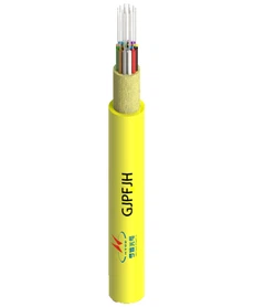
A hybrid fiber optic cable is a specialized cable built for network infrastructure. It packs delicate glass optical fibers for data and insulated copper wires for electrical power inside a single protective outer jacket.
Because both lines share one jacket, technicians can send electric power and multi-gigabit data to distant devices in a single pull. This saves installation time. It also clears up crowded cable pathways. Building these cables takes careful work. Manufacturers often add aramid yarn for strength and pack the parts into separate buffer tubes. This design keeps the heavier copper wires from crushing the fragile glass fibers or causing signal loss when workers pull the cable tight during installation.
This technology is not brand new, but modern edge networking has made it much more popular. Sumitomo Electric built the first versions in 1978 to solve tough power and communication problems in early industrial plants. Today, standard cable designs combine 1 to 24 individual optical fibers with 2 to 12 copper conductors. This variety lets engineers choose different data setups and backup power options depending on the remote hardware they need to run.
Beginner technicians often get confused by the industry terms. Many community users correctly point out that HFC, which stands for Hybrid Fiber-Coaxial, is not a hybrid fiber cable. Official telecom documents rarely explain this difference clearly.
HFC describes a large-scale broadband network used mostly by cable TV and internet providers. In an HFC system, fiber optic lines run to a local neighborhood box, and separate coaxial cables cover the final stretch to individual homes. The fiber and coax lines in an HFC network are separate physical cables placed in different parts of the system. In contrast, the composite cable we are discussing here holds both data fibers and power wires side by side inside the very same outer jacket from start to finish.
Where do these integrated applications make the most sense
These all-in-one cables work best in places where devices need fast data and steady electrical power, but sit far beyond the reach of normal network closets.
Fiber to the Antenna setups at 5G cell sites are a prime example. Modern cell towers mount Remote Radio Units at the very top of the structure, right next to the antennas. These radio units must send massive amounts of data down to the baseband unit on the ground, and they also need steady DC power to run their signal amplifiers. Pulling a single composite cable up the tower makes vertical cable runs much cleaner. It also reduces wind drag on the tower compared to running separate, bulky power and data lines.
Large parking lots and wide industrial yards depend on this design for security. High-end Pan-Tilt-Zoom security cameras use built-in heaters and infrared lights, which often draw more power than standard Power over Ethernet can supply. When workers mount these cameras on outer perimeter fences or light poles hundreds of meters away from a power source, standard twisted-pair network cables simply stop working.
Outdoor Wi-Fi access points across large campuses face the same issue. Setting up dense wireless coverage in stadiums, college quads, or shipping yards means mounting gear in spots that do not have regular wall outlets.
This cabling is made specifically for low-voltage setups. It usually follows Class 2 electrical rules that handle 57 VDC or up to 100 V. Engineers place a main power supply in the central telecom room and push DC electricity through the dedicated copper wires. This setup completely bypasses the 100-meter physical distance limit of regular twisted-pair PoE cables. The glass fiber carries high-speed data across long distances with almost no signal loss, while the copper wires are sized to carry the exact electric current the remote device needs.
How to size the copper conductors for your power budget
The most critical engineering choice is matching the thickness of the copper wire to the device's power needs and the total length of the cable run. The American Wire Gauge system sets the standard thickness for copper wires, which directly controls their electrical resistance.
The copper wires in these composite cables usually range from 12 to 20 AWG. A lower AWG number means a thicker wire. Thicker wires have less resistance to direct current, so they can carry electrical power over longer distances before voltage drops low enough to shut down the device.
When planning a power budget, engineers cannot look only at how many watts a device uses during normal operation. You must always leave a 20 percent power margin above the device's listed peak power draw. This safety margin is necessary to handle temporary startup surges, which engineers call inrush current.
When a remote radio unit turns on its power amplifiers, or when a PTZ camera runs its motors and internal heater at the same time in freezing weather, the instant current draw jumps sharply. If you size the copper wire only for the device's normal running load, this sudden startup spike causes a temporary voltage drop. That drop will trap the device in an endless reboot loop.
The link between wire size, power delivery, and maximum distance follows strict physical rules.
| Conductor Gauge (AWG) | Power Delivery (W) | Max Distance |
|---|---|---|
| 12 AWG | 75W | 457m (1,500 ft.) |
| 16 AWG | 75W | 182m (600 ft.) |
| 20 AWG | 75W | 71m (235 ft.) |
As the table shows, 12 AWG conductors can carry 75W of power out to 457m (1,500 ft.). If you switch to a much thinner wire, 20 AWG conductors can only carry that same 75W of power to about 71m (235 ft.). Choosing the right size means balancing the higher price and heavier weight of thick copper against the actual distance of your project.
Calculating voltage drop for direct current power
You must understand how direct current behaves if you want a long-distance cable installation to work. Alternating current is different because equipment can step it up to high voltages for efficient travel and step it back down at the end. Low-voltage DC power cannot do that. Instead, it loses voltage steadily across every single meter of the wire.
This loss follows Ohm's law, which states that voltage drop equals current multiplied by the total resistance of the wire. A copper wire's resistance grows as the wire gets longer, but drops as the wire gets thicker.
In a DC circuit, electricity must travel out along the supply wire to the device and come all the way back along the return wire. Because of this round trip, the wire length you use to calculate resistance is always twice the actual physical length of the cable run.
Long runs and thin wires create high resistance, which turns a lot of electrical power into wasted heat. If the voltage drops below the minimum level the remote equipment needs, the gear simply will not turn on. It will stay dead no matter how powerful the main power supply in your telecom closet is.
Real-world tests on cell tower gear show these physical limits clearly. Consider a standard 300W Remote Radio Unit running at 48V DC and drawing 6.25A of current. With a 2.5mm² conductor, its maximum working distance is only 130m. If you need to power that exact same 300W unit on a taller tower or across a wider roof, you must upgrade to a thicker 6.0mm² conductor. That thicker wire pushes the maximum working distance out to 310m for the same 48V DC, 6.25A setup.
| Metric / Parameter | Value / Tool / Standard | Operational Impact |
|---|---|---|
| Standard Reference | IEC 60228 | Defines standard conductor cross-sectional areas and resistance limits. |
| Standard Reference | IEEE 802.3bt | Specifies four-pair power delivery parameters for high-draw edge devices. |
| Copper Resistivity | 0.0175 Ω·mm²/m | Base reference value for calculating wire loop resistance at 20°C. |
| Temperature Coefficient | 0.00393 per °C | Copper resistance increases as ambient outdoor temperatures climb. |
| Verification Tool | Fluke 1587 FC | Measures line resistance and insulation integrity before connecting load. |
| Verification Tool | Keysight 34461A | Confirms loaded terminal voltage against device input specs. |
| Operating Threshold | 40.5V | Minimum functional input voltage cutoff for nominal 48V telecom gear. |
| Operating Threshold | 57.0V | Maximum allowable output setting on adjustable base station rectifiers. |
| Failure Symptom | Boot-looping | Occurs when load startup surges drop terminal voltage below cutoff. |
| Failure Symptom | Thermal throttling | Edge hardware reduces throughput due to erratic voltage fluctuations. |
| Conductor Size | 10.0mm² | Extends functional range beyond 500m for a 6.25A circuit. |
| Conductor Size | 4.0mm² | Intermediate wire gauge providing 200m reach for 300W equipment. |
| Conductor Size | 16.0mm² | Recommended cross-section for high-power multi-band tower arrays. |
Field engineers often warn in telecom forums that composite DC and fiber cables carry too little DC power over long runs because their internal wires are thin. Official datasheets often assume perfect temperatures and ideal voltages, which ignores the extra resistance found in real outdoor environments. If an engineer tries to run power-hungry edge devices over 16 AWG or 18 AWG composite cables across a large industrial park, the heavy voltage drop will leave the remote devices with no power.
Physical limitations and electrical code requirements
Combining power and data in one jacket solves many layout problems, but it introduces strict safety rules and physical limits you must follow.
The strictest rule controls the type of electricity you can legally and safely send through the cable. Even if the insulation on an individual copper wire is rated for up to 600V, you cannot run standard 120V AC wall power through these low-voltage composite cables.
The National Electrical Code demands strict separation between high-voltage power lines and low-voltage data cables. Running high-voltage alternating current directly alongside unshielded data fibers can cause heavy signal interference. It also creates a dangerous shock hazard if the outer jacket gets damaged. These composite cables are tested, listed, and rated only for Class 2 or Class 3 power-limited circuits. Trying to send standard AC mains power through these wires breaks NEC Article 725 and will instantly fail a building inspection.
Outdoor weather creates another safety challenge. When you run these cables outside along tall cell towers, stadium light poles, or open building roofs, the long copper wires act like giant antennas for static electricity and lightning strikes.
To keep equipment from getting destroyed, engineers must put direct current Surge Protection Devices at both ends of an outdoor cable run. You must ground one surge protector at the top of the tower right before the cable plugs into the radio unit or camera housing. Then, you must install a second surge protector at the bottom right where the cable enters the ground-level equipment rack. If you skip this two-sided protection, a nearby lightning strike can send a massive voltage spike down the copper wires and fry the expensive network gear in your central room.
Deciding between integrated cables and separate infrastructure runs
When planning a new installation, network designers must weigh the trade-offs between pulling a single all-in-one cable or running separate fiber and power cables through the same conduit path.
Using a single composite cable cuts down on labor costs. Pulling one jacket through underground pipes or clamping one cable to aerial support wires takes less time. It needs fewer workers, and it puts less pulling tension on the line than handling two separate cables. A single cable also takes up less space inside the conduit, which helps you stay within legal conduit-fill limits.
Buying and shipping these cables is straightforward. You can order bulk cable on large wooden reels for long trenches, or you can buy Reel-In-A-Box packages holding 500 feet per box or 1,000 feet per box. These boxes work well for indoor factory setups or short outdoor runs where heavy spool equipment will not fit.
However, running separate cables gives you much better upgrade options later on. If a site runs standard single-mode fiber next to a separate, heavy-duty electrical wire, the owners can easily upgrade the power line in the future. If a new camera or sensor needs 120V AC instead of low-voltage DC, an electrician can pull new high-voltage wires through the pipe without touching the sensitive fiber optic line. With an all-in-one cable, the data fibers and power wires are permanently trapped together. Upgrading your power capacity means you must rip out and replace the entire cable, including the fiber link.
| Deployment Approach | Material Cost | Installation Labor | Future Upgradability |
|---|---|---|---|
| Single Composite Cable | Higher initial per-meter cost | Significantly lower | Severely limited by existing copper gauge |
| Separate Fiber and Power | Lower combined material cost | Higher due to dual pulls | High flexibility to upgrade power independently |
Your final choice depends on how long the endpoint hardware will stay in place. For setups like 5G cell towers or permanent security fences where the voltage needs will not change for a decade, the lower labor costs and space savings of an integrated cable make it the better choice. For test labs or factory floors where equipment power needs change every year, keeping your fiber data lines separate from your electrical lines saves you from costly total cable replacements down the road.