






A fiber optic splice closure creates a protected enclosure around fiber splices and cable transitions. Depending on the model, it can support butt, inline or branch splicing while organizing splice trays, buffer tubes and fiber slack.
The main functions of a splice closure are to:
- Protect fusion splices and splice trays from water, dust, impact and mechanical movement.
- Provide organized fiber routing and sufficient slack storage.
- Secure the cable sheath and strength members.
- Seal cable entry points against moisture and environmental exposure.
- Allow future re-entry, cable additions or maintenance when required.
Environmental protection depends on the complete closure system. The housing, cable retention components, splice trays, entry seals, fasteners, brackets and installation procedure all affect long-term performance.

Fiber Optic Splice Closure Selection Criteria
Before choosing a closure, confirm the following project requirements:
| Selection factor | What to verify |
|---|---|
| Installation environment | Aerial, pole-mounted, wall-mounted, duct, handhole, manhole, direct-buried or ground installation. |
| Splice configuration | Butt, inline, branch or tap-off arrangement. |
| Fiber and splice capacity | Fiber count, single-fiber or ribbon splices, tray quantity and future expansion requirements. |
| Cable diameter | Minimum and maximum cable diameter supported by the port, grommet or heat-shrink sealing kit. |
| Port configuration | Number of main, branch and drop cable ports, including unused-port sealing requirements. |
| Sealing method | Gasket, gel, mechanical grommet, heat-shrink or a manufacturer-specific combination. |
| Mechanical protection | Cable retention, strength-member anchoring, crush resistance, vibration, torsion and wind loading. |
| Maintenance requirements | Re-entry frequency, cable addition, replacement parts, pressure testing and field repair procedures. |
Manufacturer documentation should be reviewed before procurement. For example, a closure installation procedure may specify cable diameter limits, port configurations, splice-tray capacity and the permitted installation environments. Review a manufacturer splice closure installation procedure.

Dome vs. Inline Fiber Optic Splice Closures
Dome Splice Closures
Dome closures generally use a vertical housing with a base and removable dome. They are often selected for pole-mounted, wall-mounted or other vertical installations, but the approved application depends on the individual product design.
The internal layout may provide space for multiple splice trays, expressed buffer tubes and branch cables. When selecting a dome closure, check the available tray height, cable entry arrangement, mounting method and re-entry procedure.
Inline Splice Closures
Inline closures usually have a horizontal or elongated housing. They can be convenient for straight-through cable routes, ducts, handholes and some aerial applications where the main cable enters and exits along the same axis.
Inline and dome designs should not be treated as fixed substitutes for specific installation environments. Some closure families are approved for more than one application, including underground, direct-buried and aerial installations. Confirm the permitted orientation, cable entry arrangement and environmental qualification in the product documentation. See typical fiber optic closure applications.
Selecting a Closure by Installation Environment
Aerial and Pole-Mounted Installations
An aerial splice closure must withstand UV exposure, wind-induced vibration, temperature cycling and mechanical loads transferred through the cable and mounting hardware.
Verify the following points before installation:
- The closure is approved for aerial or pole-mounted use.
- The bracket supports the closure without allowing repeated rubbing.
- The cable anchoring method can withstand the expected mechanical load.
- The closure orientation prevents unnecessary stress on the cable entries.
- The internal fiber routing maintains the required bend radius.
For environmental qualification, refer to the applicable standard rather than relying only on a general IP claim. IEC 61753-111-07 defines performance tests for sealed aerial closures, including sealing and mechanical tests.
Duct, Handhole and Manhole Installations
Closures installed in ducts, handholes or manholes may experience standing water, condensation, mud, cable movement and repeated access during network expansion.
Check whether the closure is intended for a wet or submerged location, whether unused ports can be resealed and whether the splice-tray layout provides enough slack for future maintenance.
Direct-Buried and Subterranean Installations
Direct-buried closures require protection against soil pressure, impact, moisture, temperature changes and possible exposure to contaminated fluids. A thicker housing alone does not prove that a closure is suitable for direct burial.
The product should be selected according to its tested environmental performance and the project installation conditions. IEC 61753-111-09 identifies test requirements for sealed subterranean closures, while IEC 61753-111-08 covers sealed ground closures.
Fiber Closure Sealing Methods
Gasket Sealing
Gasket systems use compression between closure components or around cable entry areas. The gasket must be compatible with the closure design and the supported cable diameter.
A damaged, contaminated or incorrectly seated gasket can create a leakage path even when the closure housing appears undamaged. Inspect the gasket before every re-entry and replace it when the manufacturer requires replacement.
Gel Sealing
Gel-sealed closures use a preformed or integrated gel system around cable entry points. Gel may accommodate certain cable-size variations, but the permitted diameter range, cable preparation and re-entry method remain model-specific.
Heat-Shrink Sealing
Heat-shrink systems use a heat-shrink sleeve and sealing adhesive to create a cable entry seal. They require correct cable preparation, suitable heating equipment and sufficient heating time.
Improper heating can damage the cable sheath, weaken the adhesive seal or create uneven sealing around the cable entry.
Mechanical and Grommet Sealing
Mechanical seals and grommets use compression around the cable. They may support easier re-entry, but the correct insert, port size and tightening sequence must be specified by the closure manufacturer.
Do not assume that additional silicone, mastic or waterproof tape improves every closure. If the closure has a tested sealing system, use the specified materials and installation sequence. A manufacturer installation procedure may specifically require approved sealing components and clean sealing surfaces to prevent leakage or closure damage. Follow the specified sealing procedure.

Waterproof Fiber Optic Splice Closure Installation Procedure
- Confirm the closure model.
Check the approved application, splice capacity, port arrangement, cable diameter range and sealing kit.
- Inspect all components.
Check the housing, gasket, grommets, gel components, heat-shrink sleeves, clamps, trays and fasteners for damage or contamination.
- Prepare the cable carefully.
Follow the specified sheath-removal length. Do not cut or kink strength members, buffer tubes or fibers.
- Secure the cable.
Anchor the strength member and cable sheath using the supplied retention system. The waterproof seal should not carry mechanical loads that belong to the cable clamp.
- Install the entry seal.
Use the correct grommet, gel, gasket or heat-shrink component for the actual cable diameter. Keep sealing surfaces clean and free from dirt, fibers and unapproved lubricant.
- Route and protect the fibers.
Maintain the required bend radius, organize buffer tubes and secure splice trays without pinching the fibers.
- Close the housing.
Tighten bolts, clamps or latches in the specified sequence and torque range. Avoid uneven compression around the sealing surface.
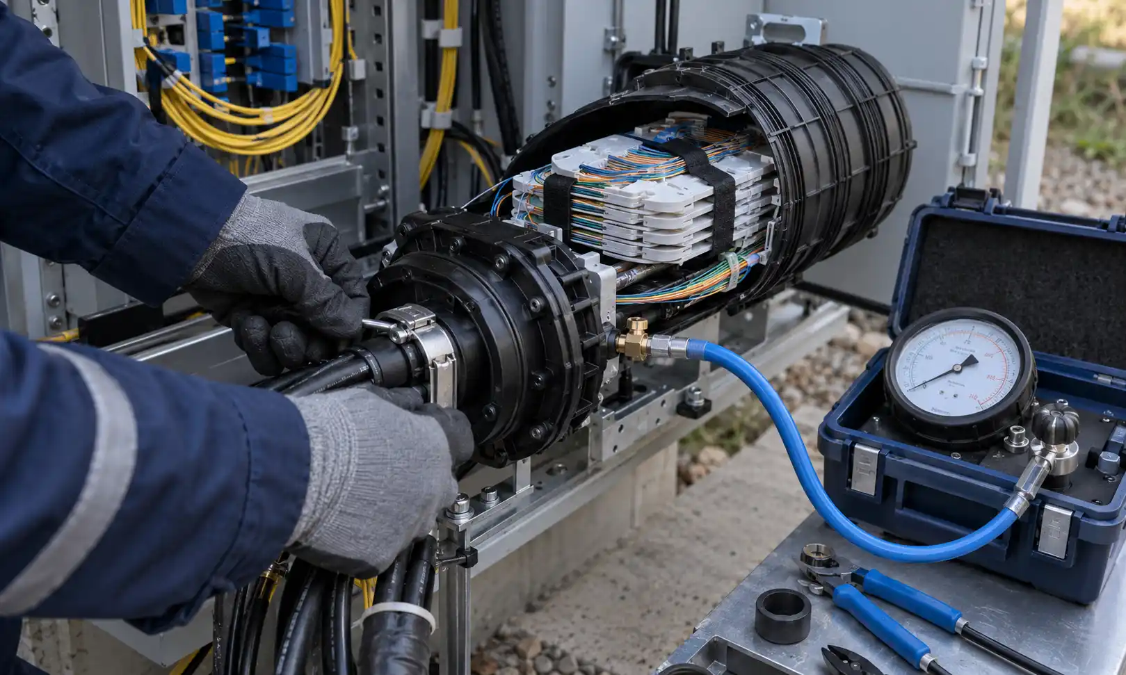
- Perform the specified leak test.
If the closure includes a test valve, use the manufacturer's approved pressure, test medium and test duration.
- Document the installation.
Record the closure model, cable diameters, sealing components, installation date, installer, test result and photographs of the completed seal.
Leak Testing and Maintenance
A visual inspection alone cannot verify sealing performance. Where the closure design supports it, perform the specified pressure or leak test after assembly and after re-entry.
Use only the approved test medium and pressure. Excessive pressure can damage the enclosure or produce an inaccurate result.
During maintenance, inspect:
- Cracks, deformation or UV damage on the housing.
- Displaced, hardened or damaged gaskets.
- Loose clamps, brackets or cable-retention points.
- Water marks, corrosion, condensation or contamination inside the closure.
- Movement or abrasion at cable entry points.
- Pressure loss during an approved leak test.
- Changes in optical attenuation identified through network testing.
Inspection intervals should be determined by the network owner's maintenance program, installation environment, closure design and the consequences of failure. A single universal inspection interval is not suitable for every project.
Common Splice Closure Sealing Failures
| Failure symptom | Possible cause | Recommended check |
|---|---|---|
| Water inside the closure | Damaged gasket, incorrect cable diameter, contaminated sealing surface or incomplete closure compression. | Inspect the seal, verify the approved cable range and repeat the specified leak test. |
| Repeated pressure loss | Cracked housing, loose fastener, poor cable-entry seal or damaged test valve. | Check the entire enclosure instead of replacing only the visible gasket. |
| Fiber attenuation after re-entry | Excessive bending, pinched fibers, poor tray routing or insufficient slack. | Inspect bend radius, tray routing and splice protection. |
| Cable movement at the entry port | Improper cable retention or incorrectly fitted strength-member clamps. | Verify cable retention separately from the waterproof seal. |
| Seal damage after installation | Unapproved tape, mastic, lubricant, heat or cutting method. | Follow the original manufacturer procedure and replace damaged specified components. |
Frequently Asked Questions
Is a dome closure always better for aerial installation?
No. A dome closure may suit a particular pole-mounted layout, but the correct choice depends on the manufacturer's approved application, mounting method, cable entry configuration and environmental testing.
Does a thicker shell automatically make a closure waterproof?
No. Waterproof performance depends on the complete sealing system, cable retention, closure assembly and verified environmental tests. Shell thickness alone is not a reliable selection criterion.
Can extra waterproof tape or mastic be added to any splice closure?
Not automatically. Use additional materials only when they are specified or approved for that closure. Unapproved materials may interfere with the tested sealing system or future re-entry.
How should I match a closure to an optical cable?
Check the cable diameter range, port and grommet configuration, cable retention method, fiber count, splice capacity and required bend radius. The closure should also support the project's splice topology and future cable additions.
Which standards should be checked?
For sealed closures, review the relevant IEC environmental category and the manufacturer's product qualification. Depending on the project, also check Telcordia requirements, operator specifications and local installation standards.
Conclusion
Selecting a fiber optic splice closure requires more than choosing a dome or inline housing. The decision should match the installation environment, splice configuration, fiber capacity, cable diameter, entry ports, cable-retention system, sealing technology and maintenance plan.
Waterproof reliability comes from using the approved sealing components, following the specified assembly sequence and completing the required leak test. For project procurement and installation, the manufacturer's installation manual and the applicable environmental performance standard should take priority over generic sealing advice.