



Which ADSS Fiber Cable Suits Installations
Choosing the right ADSS fiber cable depends on three critical factors: span length, voltage environment, and climate conditions. Installations under 110 kV typically use standard PE-jacketed cables, while 220 kV and above require AT (anti-tracking) jackets to prevent dry-band arcing. Span length determines whether you need single-jacket designs for shorter distributions (under 350 feet) or double-jacket construction for transmission-grade spans exceeding 1,000 feet.
The choice isn't just about specifications. A 2024 industry analysis shows that dry-band arcing remains the leading cause of failures on high-voltage lines, with even a few arcing incidents causing severe permanent jacket damage. This makes jacket selection arguably more critical than tensile strength for many installations.
ADSS Fiber Cable Selection by Voltage Level
Voltage level creates the most significant differentiation in ADSS cable selection because it directly impacts the electrical stress on the cable jacket.
Low to Medium Voltage Installations (Below 110 kV)
For installations on 110 kV lines, space potential should not exceed 15 kV at the suspension point. Standard polyethylene (PE) jackets handle these environments effectively because electrical field stress remains manageable. These cables cost 15-25% less than track-resistant alternatives and perform reliably when properly positioned on the tower.
Distribution networks typically fall into this category. The lighter electrical environment allows installers to focus primarily on mechanical requirements rather than electrical corrosion risks. PE jackets provide excellent UV resistance and moisture protection, with typical service lives of 25-30 years in these applications.
High Voltage Transmission Lines (110-220 kV)
On 220 kV lines, space potential must not exceed 20 kV, and anti-tracking jackets become mandatory for lines 110 kV and above. The step up in voltage creates conditions where moisture on the cable surface forms conductive paths. When these paths dry unevenly, high-resistance "dry bands" form at support points.
Track-resistant jackets incorporate carbon black and other additives that prevent the carbon tracking that leads to jacket erosion. Track-resistant outer jackets are specifically designed for high voltage transmission lines with space potential values up to 25 kV. The investment in AT jackets prevents the catastrophic failures that can occur within months in harsh voltage environments.
Ultra-High Voltage Lines (Above 220 kV)
Installations on 330 kV, 500 kV, or higher transmission lines require not just AT jackets but also careful suspension point selection and often additional anti-corona rings. Dry-band arcing becomes significantly more likely for cables installed under transmission voltage lines of 220 kV and above.
The electrical field varies from maximum at mid-span to zero at grounded supports. Installers must use electromagnetic field calculation software to identify low-field zones on towers. Simply specifying the correct cable isn't enough-placement determines whether the installation succeeds or fails within its first few years.
Span Length Determines Structural Design
Mechanical design varies dramatically based on the distances cables must span between support structures.
Short Span Distribution (Under 350 Feet)
Single jacket designs are intended for shorter pole-to-pole span lengths in distribution environments. Flex-Span and similar products use a single protective layer, reducing diameter and weight. This matters because distribution poles have lower load capacity than transmission towers.
These cables typically incorporate 6-144 fibers with tensile ratings of 600-3,000 pounds. The aramid yarn strength members provide adequate support for spans of 100-350 feet while keeping the cable light enough to avoid pole loading issues. Tangent clamps work effectively in these applications when angle changes remain under 15 degrees.
Medium Span Applications (350-1,200 Feet)
Standard span installations require more robust construction. ADSS cables are designed to be strong enough to allow lengths of up to 700 meters to be installed between support towers. This translates to roughly 2,300 feet maximum, though practical installations rarely exceed 1,200 feet without intermediate supports.
Double-jacket designs provide the necessary strength. The inner jacket protects fibers while the outer jacket handles environmental stress and mechanical loading. Aramid yarn content increases significantly, with tensile ratings reaching 8,000-15,000 pounds. This additional strength prevents excessive sag under ice loading while maintaining acceptable tension levels.
Long Span Transmission (Over 1,200 Feet)
Long span installations can exceed 1,000 meters with maximum spans over 1,000 meters possible with proper design. These applications push ADSS cables to their mechanical limits. Cable diameter increases to 16-20mm to accommodate the reinforcement required.
Designers must account for worst-case loading scenarios: maximum ice accumulation, high wind, and minimum temperature occurring simultaneously. Professional span calculation software becomes mandatory. The cables must not sag low enough to create clearance violations, yet excessive tension accelerates fatigue. Cables must be designed for the worst-case combinations of temperature, ice load, and wind.
Environmental Selection Criteria for ADSS Fiber Cable
Geography and climate significantly influence which ADSS cable performs optimally.
Coastal and High-Contamination Areas
Wetting conditions near industrial plants or saltwater have more severe effects on jacket resistance than freshwater rain or fog. Salt deposits create highly conductive surface layers that dramatically increase leakage current and dry-band formation risk.
Coastal installations within 10 miles of saltwater require AT jackets regardless of voltage level. The combination of salt spray and normal moisture creates aggressive electrical stress even on 35 kV distribution lines. Anti-corona coils at suspension points add another layer of protection by reducing surface electric field intensity.
Industrial zones with chemical emissions face similar challenges. Acid and alkaline contaminants accelerate polymer degradation. Selecting cables with enhanced jacket formulations extends service life from 15-20 years to 25-30 years in these demanding environments.
Extreme Temperature Regions
ADSS cables must operate across temperature ranges typically from -40°C to +70°C to accommodate extreme climate zones. The challenge isn't just the extremes but the cycling between them. Daily temperature swings cause expansion and contraction that creates micro-movements in the cable.
Gel-filled buffer tubes handle temperature cycling better than dry core designs in extreme climates. The gel absorbs some movement and prevents fiber damage from compression during cold snaps. However, gel adds weight, which matters for span calculations.
Arctic and desert installations both face UV exposure challenges. UV-resistant outer jackets are specifically designed to resist solar irradiation damage. Carbon black loading in the jacket provides photo-protection, preventing the polymer chain breakdown that leads to brittleness and cracking.
High Wind and Ice Loading Zones
On long spans where utilities experience conductor galloping caused by sustained high wind, dampers may need to be installed on ADSS cable also. Wind-induced aeolian vibration creates high-frequency oscillations that cause fatigue at suspension points.
Ice accumulation multiplies cable weight several times over. A cable designed for 0.5 inches of radial ice might see its weight triple during ice storms. This affects not just the cable but also pole and tower loading. Installers must verify that structures can handle worst-case loading before specifying long spans.
Anti-vibration dampers become mandatory on spans exceeding 600 feet in high-wind areas. These devices absorb vibrational energy, preventing the metal fatigue in aramid yarns that leads to eventual cable failure. The investment in dampers costs far less than replacing a failed cable.
Fiber Count and Network Architecture
The number of fibers needed shapes cable selection in ways beyond just capacity.
Low Fiber Count (6-48 Fibers)
Small fiber counts allow for the most flexible designs. Gel-filled tubes are reverse-oscillated to allow slack for mid-span access with cables supporting up to 288 fibers. With only 6-48 fibers, central tube designs work effectively, simplifying splicing and reducing cable diameter.
These cables suit rural deployments and initial network builds where growth projections remain uncertain. The smaller diameter reduces wind loading and makes handling easier during installation. Minimum bending radius decreases, allowing tighter routing around obstacles.
Distribution networks often start with 24 or 48-fiber cables, reserving half the capacity for future growth. This prevents the need to install additional cables as the network expands, which proves far more expensive than using surplus capacity in the original installation.
Medium Fiber Count (48-144 Fibers)
This range represents the sweet spot for most utility and telecommunications applications. Loose tube stranded construction becomes standard, with 6-12 fibers per buffer tube. Stranded structure provides superior waterproofing and offers more flexible installation methods, making this cable type more suitable for large-span applications.
The multi-tube design allows selective fiber access without disturbing the entire cable. Technicians can open a single buffer tube for splicing while leaving others untouched. This modularity proves valuable for phased network deployment and makes troubleshooting simpler.
Weight and diameter increase proportionally with fiber count, requiring careful span calculations. A 144-fiber cable weighs roughly three times more than a 24-fiber equivalent, significantly impacting sag and tension requirements.
High Fiber Count (144-288 Fibers)
Single jacket designs accommodate up to 288 fibers in gel-filled tubes, though these installations require careful planning. The cable diameter reaches 16-20mm, creating substantial wind loading. Only transmission towers and reinforced utility poles can support these cables across meaningful spans.
Ribbon fiber construction becomes attractive at high counts. Twelve-fiber ribbons stacked in a central tube allow 288 fibers in remarkably compact designs. Mass fusion splicing speeds installation, which matters when deploying hundreds of fibers. The trade-off comes in reduced flexibility and higher skill requirements for splicing teams.
High-count cables make sense for trunk routes and high-capacity corridors but prove wasteful for distribution. The 40-60% cost premium over 144-fiber alternatives only justifies itself when capacity utilization exceeds 60% within five years.
Installation Method Considerations
How the cable will be installed influences which design performs best.
Live-Line Installation Requirements
ADSS cable can be installed using live-line methods on an energized transmission line. This capability drives much of ADSS adoption, as power utilities can't afford multi-day outages for telecommunications projects.
Live-line work demands all-dielectric construction-any metallic components create unacceptable safety risks. The cable must remain at safe distances from energized conductors during installation. If line voltage is 230 kV or greater, grounding the sheaves may be required during installation.
Installation crews need specialized training and equipment. Bull wheel tensioners with constant tension monitoring prevent damage during pulls. Wire mesh grips distribute pulling force across the cable's aramid strength members without crushing the outer jacket. These requirements add 15-25% to installation costs compared to de-energized work.
Aerial Versus Duct Applications
While ADSS primarily serves aerial installations, some designs work in duct systems. Flex-Span ADSS cables are designed for aerial distribution power lines as well as underground duct applications. The self-supporting structure proves unnecessary in ducts, but the all-dielectric property and ruggedized jacket still provide value.
Duct installations eliminate UV exposure, ice loading, and wind stress. This allows using lighter designs with lower tensile ratings. The same cable rated for 400-foot aerial spans might support 2,000-foot duct pulls because bending stress becomes the primary limitation rather than tensile loading.
Hybrid routes that transition from aerial to duct face unique challenges. The cable must handle both environments, typically requiring aerial-grade specifications throughout. Transition points need careful sealing to prevent water infiltration from underground sections migrating into aerial spans.
Retrofit Versus New Construction
New power line construction allows optimal ADSS placement. Designers can specify suspension points in low electrical field zones and ensure adequate clearance from phase conductors. The most favorable location for installation on support structures is an area of relatively low field voltage, which can be determined using electromagnetic field voltage calculation programs.
Retrofit installations work within existing tower geometry. This often forces compromises. Suspension points may sit in sub-optimal electrical field zones, requiring enhanced jacket specifications to compensate. Limited clearance might necessitate shorter spans or intermediate supports.
Overlashing existing cables provides another retrofit option. All cables must be securely lashed to the messenger and cables with no loose hanging cables anywhere along the span. This approach allows rapid deployment but limits cable size and increases wind loading on support structures.
Construction Type Trade-offs
Internal cable architecture creates distinct performance profiles.
Central Tube Design
Single large tubes containing all fibers suit short to medium spans in benign environments. Manufacturing simplicity reduces costs 10-15% compared to stranded alternatives. The central tube design provides excellent fiber protection in the core while simplifying field access.
Fiber count limitations present the main drawback. Central tube construction becomes impractical beyond 48-72 fibers due to diameter constraints. The design also concentrates all fibers in one location, meaning any penetration of the tube compromises the entire cable.
Water blocking in central tube designs typically uses super-absorbent powder rather than gel. This reduces weight but provides less fiber mobility within the tube. Temperature-induced expansion and contraction can create higher fiber strain compared to gel-filled alternatives.
Stranded Loose Tube Construction
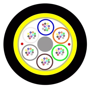
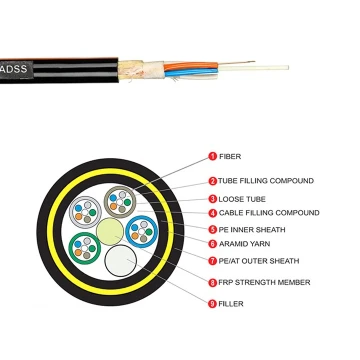
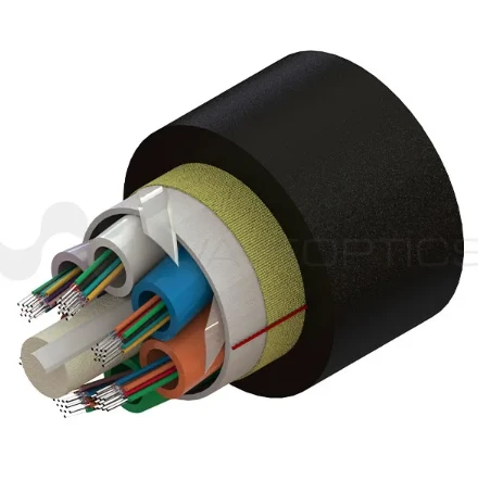
Stranded structure ensures waterproof performance and has more laying methods, with longer fiber length making this type more suitable for large-span applications. Multiple buffer tubes helically stranded around a central strength member distribute fibers across the cable cross-section.
Each tube contains 6-12 fibers in gel, providing individual protection and allowing selective access. The stranding pattern accommodates cable flexing and bending without concentrating stress on any single fiber. This proves critical for long spans that experience significant movement from wind and temperature changes.
Manufacturing complexity and higher material costs add 15-20% to prices for ADSS fiber cable designs with stranded construction. The larger diameter increases wind loading. These penalties only justify themselves when installation conditions demand the superior performance stranded designs provide.
Ribbon Architecture
High-density fiber ribbons-typically 12 fibers laminated together-enable compact high-fiber-count cables. Another version consists of a large central tube containing multiple flat, thin structures called fiber ribbons, with 6 or 12 fibers laminated between layers of tape-like material.
Mass fusion splicing transforms installation economics at high fiber counts. Splicers can fuse 12 fibers simultaneously rather than individually, cutting splice times by 60-75%. This matters significantly on 288-fiber trunks where traditional splicing could take days.
The rigidity of ribbons creates handling challenges. Minimum bending radius increases compared to loose tube designs. Technicians need specialized ribbon splicing equipment and training. Rural installations with limited technical resources often avoid ribbon cables despite their density advantages.
Hardware Compatibility Requirements
Cable selection connects directly to installation hardware specifications.
Dead-End and Suspension Hardware
Fittings used with ADSS cable may be tension type used at dead-ends where cable terminates or changes direction, or suspension type only holding the span weight with tension transmitted through the next span. Tension hardware must match cable diameter and tensile rating precisely.
Using undersized tension grips causes stress concentration that damages aramid yarns. Oversized grips may not engage properly, allowing cable slippage. Manufacturers provide compatibility charts specifying which hardware works with which cable models-deviating from these specifications voids warranties and creates safety risks.
A tangent clamp is used as cable attachment hardware only on spans less than 100 meters when the angle of change, either horizontal or vertical, is less than 15 degrees. Beyond these limits, full tension grips become mandatory. This influences cable selection for routes with frequent direction changes.
Vibration Control Components
Wind-induced aeolian vibration may be a factor on longer spans since ADSS cables have light weight, relatively high tension, and little self-damping. Anti-vibration dampers attach near suspension points to absorb high-frequency oscillations.
Damper specifications must match cable diameter, weight, and span characteristics. Improperly sized dampers either fail to control vibration or create their own stress concentrations. The need for dampers adds $150-300 per span to project costs, which factors into cable selection for long-span applications.
Reinforcing rods protect the cable where hardware attaches. Accessories must not be clamped directly to the cable but instead over reinforcing rods to protect the cable from electrical and mechanical damage. Rod length and stiffness vary with cable diameter, creating another hardware compatibility consideration.
Jacket Material Selection Matrix for ADSS Cables
Beyond PE and AT designations, jacket formulations vary in subtle but important ways.
Standard Polyethylene (PE)
Black PE compounds with carbon loading provide baseline UV protection and mechanical durability. These jackets handle temperature ranges from -40°C to +70°C while resisting moisture infiltration. Material costs remain low, and extrusion characteristics allow consistent manufacturing.
PE becomes brittle after extended UV exposure in high-altitude or desert installations. Five to seven years of intense sunlight begins breaking polymer chains, leading to surface crazing and eventual cracking. In moderate climates at lower elevations, PE jacketed cables regularly exceed 25-year service lives.
Chemical resistance proves adequate for most environments. PE withstands acid rain and general industrial atmospheric contamination. Exposure to petroleum products, solvents, or strong bases accelerates degradation, but such conditions rarely occur in aerial installations.
Anti-Tracking (AT) Compounds
For installation on high-voltage lines up to 275 kV, an optional track-resistant jacket is available to protect against dry-band arcing damage. AT formulations incorporate conductive fillers that prevent the carbon tracking responsible for jacket erosion.
The material balance proves critical. Too much conductivity creates leakage current problems. Insufficient conductivity fails to prevent tracking. Manufacturers guard their formulations carefully, as small variations in filler loading dramatically affect performance.
AT jackets cost 25-40% more than standard PE but prevent failures that destroy cables. The return on investment becomes obvious in high-voltage applications. Some utilities mandate AT jackets on all lines above 66 kV regardless of calculated field stress, treating it as insurance against unexpected conditions.
Enhanced Environmental Formulations
Specialized compounds address niche applications. Coastal cables use salt-resistant formulations with enhanced moisture barriers. Cold-climate jackets maintain flexibility to -50°C or -60°C, preventing cracking during Arctic winters. Desert formulations incorporate additional UV stabilizers for extreme photo-degradation environments.
These specialty compounds add 15-30% to cable costs but prove essential in extreme conditions. A standard PE jacket in Arabian Gulf summers (55°C ambient temperature, higher solar heating) fails within 5-7 years. Enhanced compounds extend this to 20-25 years, justifying their premium.
Flame-retardant (FR) variants serve installations near industrial facilities or through wildfire-prone areas. FR compounds self-extinguish when ignition sources remove, preventing cable-carried fire propagation. Building code requirements sometimes mandate FR specifications even for outdoor aerial cables.
Cost-Performance Optimization Strategies
Balancing specifications against budget constraints requires systematic analysis.
Over-Specifying Versus Right-Sizing
The temptation to "buy the best" often results in unnecessary expense. Standard ADSS cables accommodate span lengths up to 3,500 feet with double jacket designs providing additional protection for longer spans and higher strength requirements. But installing transmission-grade cable on 200-foot distribution spans wastes 40-50% of the budget.
Right-sizing means matching specifications to actual conditions plus reasonable margin. A 500-foot span in a 35 kV environment needs perhaps a 4,000-pound tensile rating. Specifying 12,000-pound cable "for future-proofing" adds cost without benefit-poles can't support longer spans, and electrical conditions won't change.
Conservative engineering suggests a 20-25% specification margin above calculated requirements. This accounts for installation error, unexpected loading, and manufacturing tolerances. Beyond this margin, additional strength just adds weight and cost.
Life-Cycle Cost Analysis
Initial cable cost represents only 30-40% of total installed cost when including labor, hardware, and equipment. Selecting cheaper cable to save $5,000 makes no sense if it requires replacement in 12 years versus 25 years for better alternatives.
Typical ADSS cable lifespan is usually 25 to 30 years, depending on environmental conditions and proper installation. Calculating net present value of replacement costs changes the economic equation. A cable costing 30% more with twice the service life delivers 40% lower life-cycle cost.
Maintenance access affects economics significantly. Long-span installations over rivers, highways, or difficult terrain make repairs expensive. Spending more initially on robust cables that require less maintenance optimizes total cost of ownership.
Volume and Project Timing
Minimum order quantities for ADSS typically start at 4 kilometers, with delivery times of 7 days for small orders and 10-20 days for quantities exceeding 100 kilometers. Consolidating purchases captures volume discounts of 15-25% on orders above 50 kilometers.
Project timing influences pricing. Cable manufacturers run production campaigns for specific designs. Ordering during these campaigns reduces costs 10-15% compared to custom production runs. Lead times also shorten from 8-12 weeks to 4-6 weeks for campaign products.
Standardizing on fewer cable types across an entire utility network enables better inventory management and technician training. While each installation might have slightly different optimal specifications, using three to four standard designs simplifies logistics and reduces overall program costs.
Installation Scenario Decision Trees
Different applications call for distinct selection approaches.
Urban Distribution Networks
Short spans (150-350 feet), moderate voltage (12-35 kV), and dense infrastructure characterize urban distribution. Single-jacket designs with 48-72 fibers handle most requirements. PE jackets suffice unless coastal proximity or industrial contamination exists.
Urban installations face unique challenges. Numerous attachment points create more suspension hardware requirements. Trees and buildings create clearance constraints. Aesthetic considerations sometimes drive selection toward smaller diameter cables even when unnecessary from technical standpoint.
Permit requirements in municipalities often specify flame-retardant materials. This adds 10-15% to cable costs but proves non-negotiable. Local codes override technical optimization, forcing selection of compliant products regardless of performance trade-offs.
Rural Broadband Deployment
The rapid expansion of telecommunication networks driven by the rise of mobile data consumption and deployment of 5G technology has significantly boosted demand for ADSS cables, which are ideal for urban and rural installations due to their ability to withstand harsh environmental conditions. Rural deployments emphasize long spans, lower fiber counts, and minimal maintenance access.
Spans of 600-1,200 feet between poles reduce infrastructure costs in sparsely populated areas. Double-jacket cables with 6,000-10,000 pound tensile ratings accommodate these distances. The all-dielectric property allows installation on existing power lines without extensive modifications.
Fiber counts of 24-48 suit rural density, with half reserved for growth. The focus shifts from capacity to reach-getting fiber to underserved areas matters more than maximizing density. Ruggedized ADSS fiber cable designs that survive with minimal maintenance for 25+ years optimize economics where technician dispatches cost $500-800 per trip.
Transmission Line Communication Systems
High-voltage transmission lines use ADSS cables because their non-metallic construction displays immunity to EMI and allows installation near high-voltage conductors. Utility companies deploy these for SCADA, protection relaying, and operational communications.
Reliability outweighs cost in transmission applications. System failures risk grid stability and cost millions in lost revenue. AT jacketed cables become standard regardless of calculated field stress. Double redundancy in fiber paths ensures communication survives cable damage.
Fiber counts typically range from 24-96, supporting multiple applications. Separate fiber pairs serve protection (highest priority), SCADA (medium priority), and telephone/data (lowest priority). This segregation prevents lower-priority traffic from interfering with critical protection signals.
Renewable Energy Integration
Wind and solar projects require aerial fiber connections at elevated transmission line altitudes. Solar farms and wind facilities need robust communication for monitoring, control, and revenue metering.
Environmental extremes challenge cable selection. Desert solar installations face extreme UV exposure and temperature swings. Offshore wind encounters salt spray and high winds. Mountain wind farms deal with ice loading and lightning exposure.
Modular designs allowing field expansion suit renewable projects. Initial installations might use 48 fibers, with capacity to add circuits as the facility expands. The 25-year planning horizon for renewable projects aligns well with ADSS service life, amortizing cable costs across the facility lifetime.
Common Selection Mistakes and How to Avoid Them
Even experienced engineers make preventable errors.
Ignoring Space Potential Calculations
Many failures stem from assuming voltage rating alone determines jacket requirements. In order to avoid high field voltages that occur close to phase conductors, the position of ADSS cable must be carefully considered before selecting where the cable will be installed on towers.
Space potential-the voltage difference between cable and ground-varies with position on the tower and changes dramatically with moisture conditions. A cable positioned near phase conductors might experience 30 kV space potential on a 220 kV line, while proper placement reduces this to 12 kV.
Using electromagnetic field calculation software costs $500-2,000 but prevents failures costing tens of thousands in emergency repairs and replacement. The analysis takes 2-3 hours per tower type and provides definitive placement guidance that informs both cable selection and installation specifications.
Underestimating Ice and Wind Loading
Cables must be designed for worst-case combinations of temperature, ice load, and wind. Using average conditions rather than 50-year worst-case creates systematic under-design. A span that looks adequate at 0.25 inches of ice fails at 0.75 inches.
Weather data from airports and weather stations provides historical extremes. Ice loading varies dramatically with elevation-mountain installations might see 2-3 inches of radial ice while valleys 10 miles away rarely exceed 0.5 inches. Local utility experience provides valuable guidance beyond standard weather data.
Safety factors on mechanical specifications should reach 2.5-3.0× calculated loads. This accounts for ice above weather service predictions, combined loading events (ice plus wind), and age-related strength degradation. Cables failing mechanical requirements typically do so during extreme weather events 5-15 years after installation.
Overlooking Future Expansion Needs
Networks evolve. Selecting cable based solely on immediate needs often necessitates adding capacity within 5-7 years. Installing a second cable costs 3-5× more per fiber than oversizing the initial cable adequately.
Reasonable fiber count planning adds 50-100% capacity margin for 10-year horizons. A network requiring 24 fibers initially should deploy 48-72. The incremental cost of additional fibers runs only 30-40% while providing doubling to tripling of capacity headroom.
Duct installations make future augmentation easier but aerial installations essentially lock in capacity. Once a span is loaded with hardware and cable, adding another cable requires near-complete reinstallation. The second cable interferes with the first, doubles wind loading, and complicates maintenance.
Frequently Asked Questions
How do I determine maximum span length for my installation?
Maximum span depends on cable tensile strength, allowable sag, and environmental loading. Start with manufacturer span charts matching your cable rating and expected ice/wind loads. For spans exceeding standard tables, use professional calculation software that models catenary curves under worst-case loading. Most utilities limit ADSS spans to 1,200 feet as a practical maximum regardless of cable strength, since longer spans create clearance and vibration challenges that offset cost savings.
Can I use the same ADSS cable for both 69 kV and 230 kV installations?
Technically yes, but economically it makes little sense. Using AT-jacketed ADSS fiber cable designed for 230 kV on 69 kV lines wastes 25-40% of your budget on unnecessary jacket specifications. Instead, standardize on two cable types: PE-jacketed for installations below 110 kV, and AT-jacketed for 110 kV and above. This provides appropriate protection while optimizing costs across your network.
What's the practical difference between gel-filled and dry core designs?
Gel-filled buffer tubes use petroleum jelly to block water penetration and provide fiber mobility within the tube. This works well for installations with temperature extremes or where water infiltration risk exists. Dry core designs use water-blocking tapes or powders, reducing weight by 8-12% and simplifying handling. Choose gel-filled for harsh environments and long spans where fiber movement matters; select dry core for benign conditions and weight-sensitive installations where pole loading becomes a constraint.
Should I specify single-mode or multimode fibers in ADSS cable?
Single-mode fibers support longer distances and higher bandwidths, making them the standard for nearly all outside plant applications. Multimode fibers cost slightly less but limit transmission to 550 meters at 10 Gbps or 1-2 kilometers at lower speeds. Unless connecting buildings on the same campus, single-mode provides far better long-term value and flexibility for future technology upgrades.
The ADSS cable market's projected growth from $1.42 billion in 2024 to $2.8-3.1 billion by 2033 reflects the technology's proven effectiveness. Success comes not from choosing the "best" ADSS fiber cable but from matching specifications to actual installation conditions-voltage environment, span requirements, climate factors, and network architecture all weigh equally in optimal selection.
Primary Information Sources
AFL Global. "ADSS Fiber Optic Cable Products." aflglobal.com
Wikipedia. "All-dielectric self-supporting cable." Last updated January 2020
Zion Communication. "What Is ADSS Cable: Types, Applications, Advantages & Installation Guide." June 2025
Verified Market Reports. "All-Dielectric Self-Supporting Cable Market Research Report 2033." June 2025
Prysmian Group. "Long Span ADSS Cable." March 2023
Corning. "Installation of Solo ADSS All-Dielectric Self-Supporting." Installation guidelines documentation
OFIL Systems. "ADSS Fiber Inspection Solutions." April 2024