

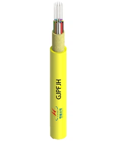


As a seasoned supplier of photoelectric composite cables, I am often asked about the intricate structure of these remarkable cables. In this blog post, I will delve into the components and design of photoelectric composite cables, shedding light on their functionality and applications.
Understanding the Basics of Photoelectric Composite Cables
Photoelectric composite cables, as the name suggests, combine both optical fiber and electrical conductors within a single cable structure. This integration allows for the simultaneous transmission of optical signals for high - speed data transfer and electrical power for various devices. These cables are widely used in a range of industries, including telecommunications, data centers, and smart grid systems.
Key Components of Photoelectric Composite Cables
Optical Fiber Unit
The optical fiber unit is the heart of the photoelectric composite cable when it comes to data transmission. Optical fibers are made of thin strands of glass or plastic that can transmit light signals over long distances with minimal loss. They are capable of carrying large amounts of data at extremely high speeds, making them ideal for applications such as internet connectivity, video streaming, and telecommunication networks.
There are different types of optical fibers used in photoelectric composite cables, including single - mode and multi - mode fibers. Single - mode fibers are designed for long - distance transmission, typically used in telecommunications backbone networks. Multi - mode fibers, on the other hand, are suitable for shorter distances and are commonly used in local area networks (LANs) and data centers.
Electrical Conductor Unit
The electrical conductor unit in a photoelectric composite cable is responsible for transmitting electrical power. These conductors are usually made of copper or aluminum due to their excellent electrical conductivity. The size and number of conductors depend on the power requirements of the connected devices.
For example, in a small - scale application such as powering a security camera, a thinner conductor may be sufficient. However, for larger devices like industrial equipment or data center servers, thicker and more robust conductors are needed to handle higher power loads.
Buffer Layer
The buffer layer is an important component that surrounds the optical fibers. Its primary function is to protect the delicate optical fibers from mechanical stress, such as bending, stretching, and compression. The buffer layer is typically made of a soft polymer material, which provides a cushioning effect and helps maintain the integrity of the optical fibers.
Armor Layer
In some photoelectric composite cables, an armor layer is added for additional protection. The armor layer can be made of materials such as steel tape or aluminum tape. The Aluminum Tape Fiber Optic Cable is a good example of a cable with an armor layer. This layer protects the cable from external damage, such as rodent bites, mechanical impact, and environmental factors. It also provides electromagnetic shielding, reducing interference between the electrical and optical components.
Outer Sheath
The outer sheath is the outermost layer of the photoelectric composite cable. It provides a protective barrier against moisture, chemicals, and UV radiation. The outer sheath is usually made of a durable polymer material, such as polyethylene or polyvinyl chloride (PVC). Different types of outer sheaths can be used depending on the environmental conditions in which the cable will be installed. For example, in outdoor applications, a UV - resistant outer sheath is required to prevent degradation from sunlight exposure.
Design Considerations for Photoelectric Composite Cables
Cable Configuration
The configuration of a photoelectric composite cable refers to the arrangement of the optical fiber unit and the electrical conductor unit. There are several common configurations, including parallel, concentric, and stranded.
In a parallel configuration, the optical fibers and electrical conductors are placed side by side within the cable. This configuration is relatively simple and easy to manufacture. The concentric configuration, on the other hand, has the electrical conductors arranged around the optical fibers in a circular pattern. This design provides better protection for the optical fibers and can reduce electromagnetic interference. The stranded configuration involves twisting the optical fibers and electrical conductors together, which improves the flexibility and mechanical strength of the cable.
Compatibility and Integration
When designing a photoelectric composite cable, compatibility and integration between the optical and electrical components are crucial. The cable must be designed in such a way that the electrical and optical signals do not interfere with each other. This requires careful selection of materials and proper shielding techniques.
For example, the buffer layer and armor layer can be designed to minimize electromagnetic interference between the electrical conductors and the optical fibers. Additionally, the cable connectors must be designed to ensure proper alignment and connection of both the optical and electrical components.
Applications of Photoelectric Composite Cables
Telecommunications
In the telecommunications industry, photoelectric composite cables are used to provide both high - speed data transmission and power to remote communication equipment. For example, in a 5G base station, a photoelectric composite cable can be used to connect the base station equipment to the power source and the fiber optic network simultaneously.


Data Centers
Data centers require a large amount of power and high - speed data transfer. Photoelectric composite cables can be used to connect servers, storage devices, and networking equipment, providing a single cable solution for both power and data transmission. This reduces the complexity of cable management and improves the overall efficiency of the data center.
Smart Grid Systems
In smart grid systems, photoelectric composite cables are used to connect power generation sources, such as solar panels and wind turbines, to the power grid. These cables can transmit both electrical power and data, allowing for real - time monitoring and control of the power grid.
Conclusion
The structure of a photoelectric composite cable is a carefully engineered combination of optical fiber, electrical conductors, and protective layers. Each component plays a vital role in ensuring the reliable transmission of both data and power. As a supplier of Composite Hybrid Fiber Optic Cable, I understand the importance of providing high - quality cables that meet the diverse needs of our customers.
If you are interested in learning more about our photoelectric composite cables or have specific requirements for your project, please feel free to contact us for a procurement discussion. We are committed to providing the best solutions for your power and data transmission needs.
References
- Grobe, R. (2007). Fiber Optic Test and Measurement. Prentice Hall.
- Neufeld, R. (2012). Electrical Wiring: Residential. Pearson.